I attempt to repair my HP 3582A Spectrum Analyzer. This Hewlett Packard instrument dates back to around 1978 and early 80’s, about as old as I am myself. Without any prior warning, one day the instrument started showing a skewed image on the CRT display, but the instrument remained fully functioning from inputs to measurements. This just seemed like a power supply or display driver issue. With the service manual in hand, I venture out in trying to repair the instrument, but only for matters to go from bad to worse…
If you like to see what is inside other laboratory equipment, check out these articles and videos: Hitachi L7450 HPLC Diode-Array-Detector Teardown, Teardown of Servomex CO2 Analyzer 1400 Series, HPLC Thermostatted Column Teardown – Dionix TCC-3000SD or Agilent Markes UNITY Thermal Desorber Teardown – Gas Chromatography.
HP 3582A Display Problems
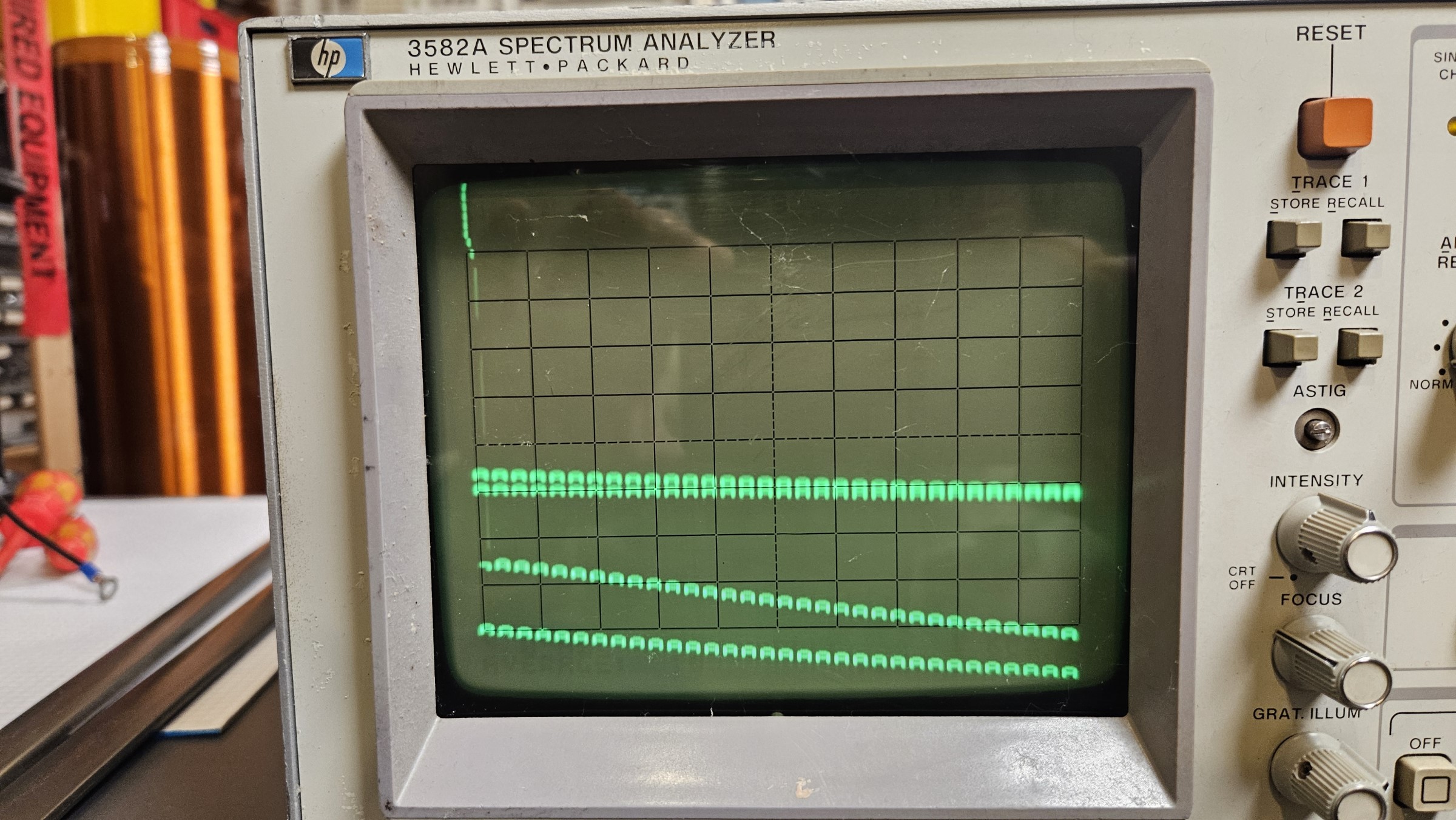
The problems with the display happened out of nowhere. The instrument has just been sitting on top of the workbench and one day when powered on, the display was skewed. The image should have shown two rows of A in the top and two rows of A in the bottom, with a square wave in the middle of those rows.
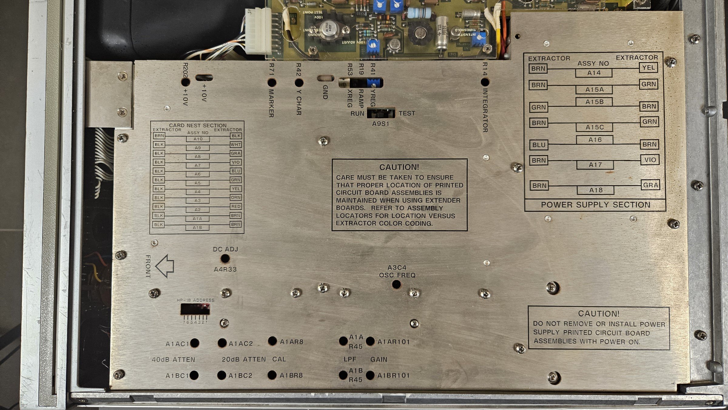
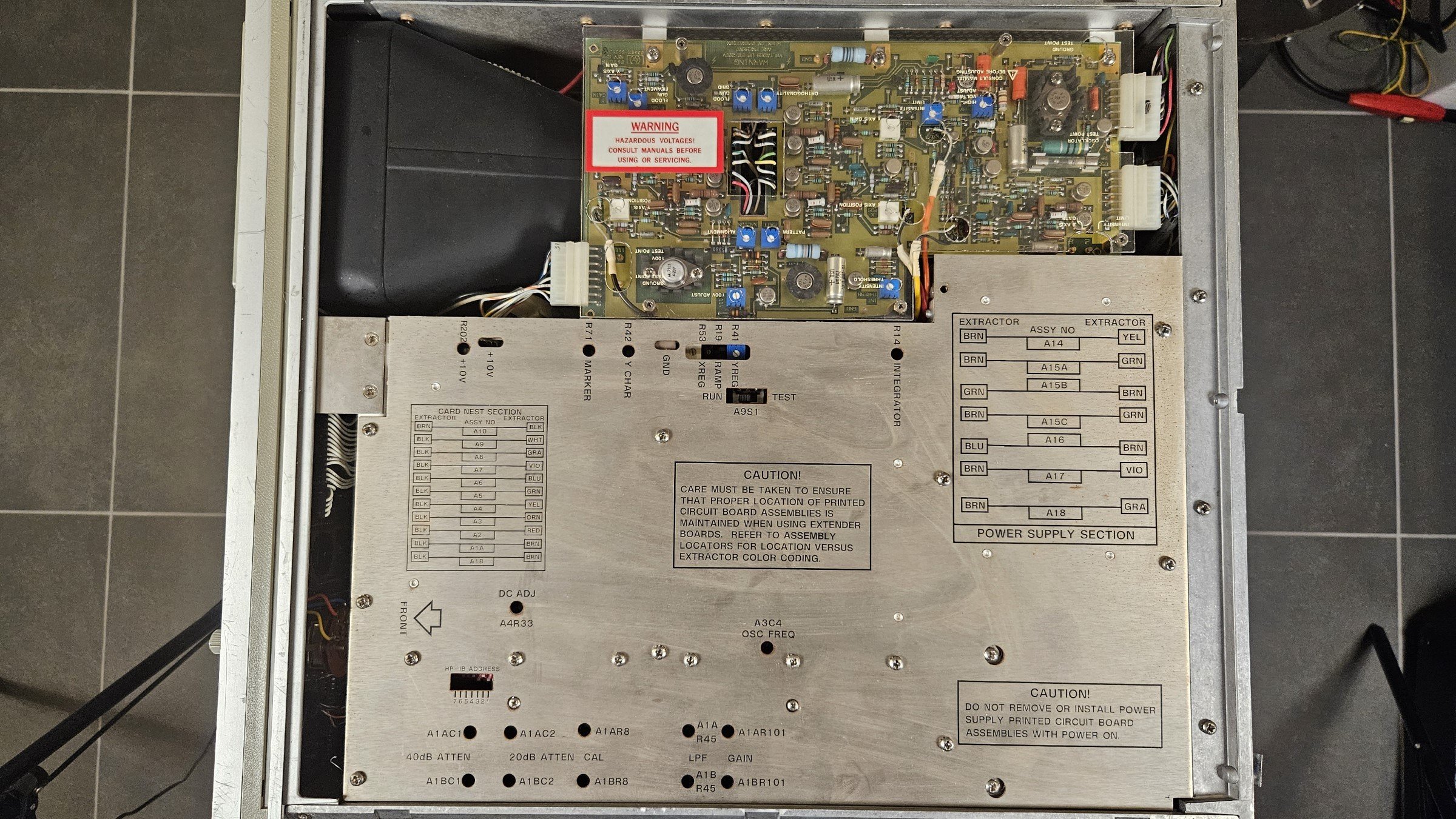
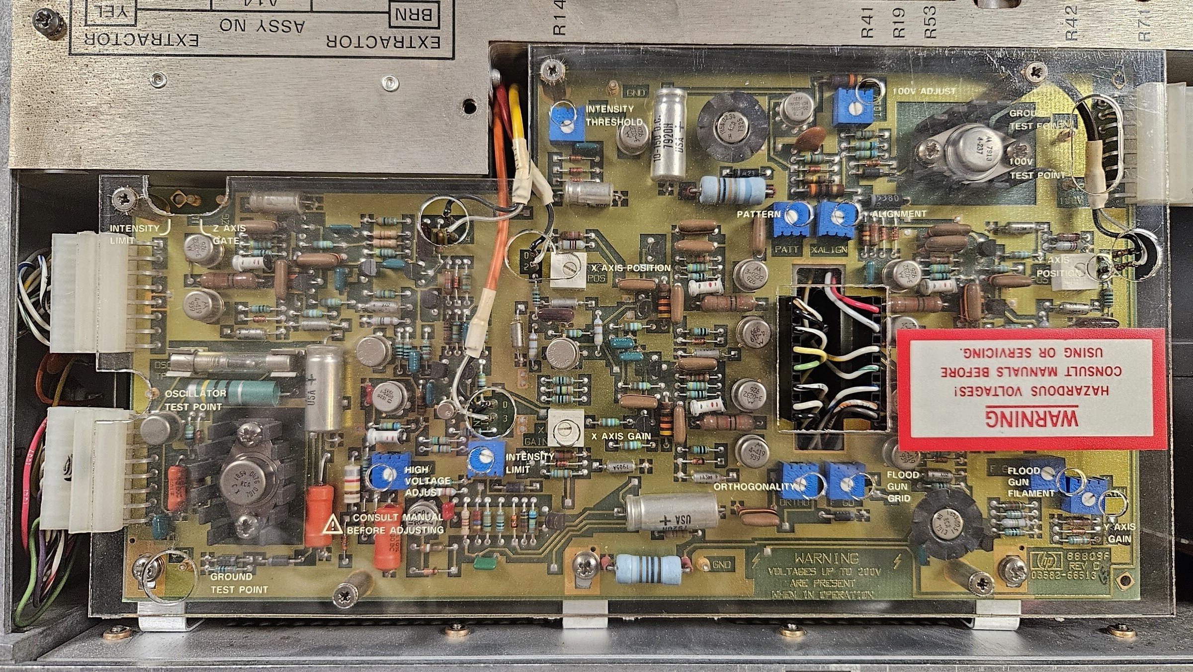
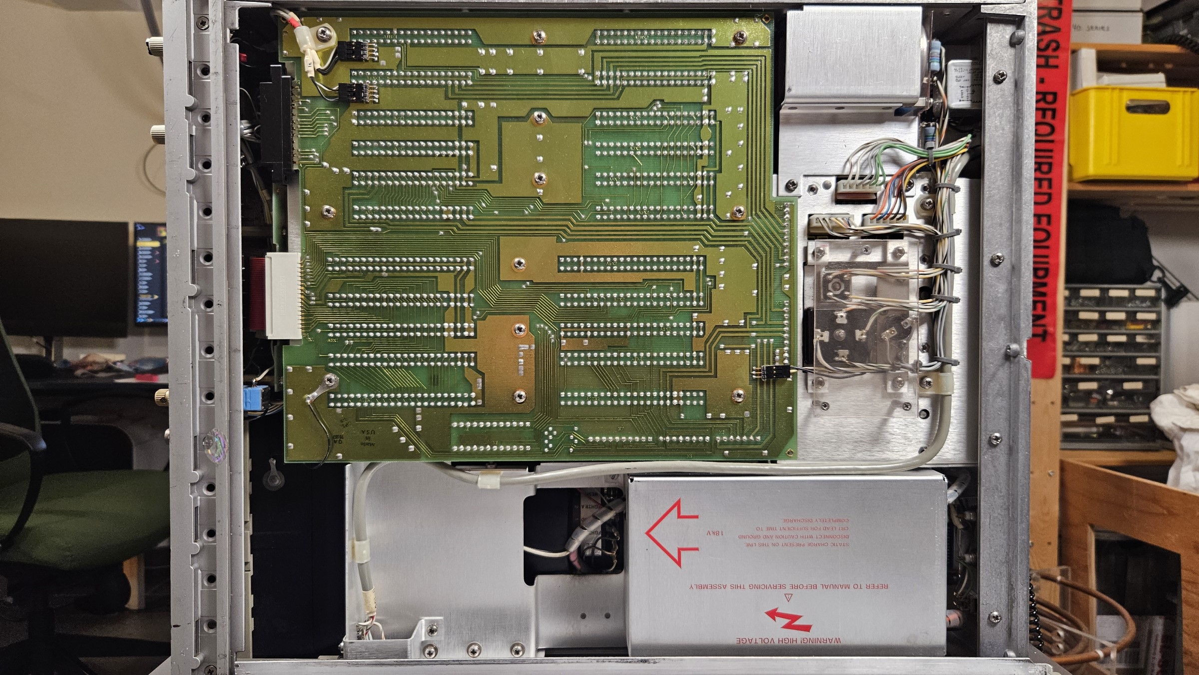
The inside of the instrument is a joy, everything is arranged for service with clear markings and color codes. The shielding plate on top has all designations and places marked out as well. The high voltage power supply and amplifier boards are neatly situated alone with the CRT and properly protected with acrylic. The card underneath the acrylic is A13, which is the XYZ amplifiers for the CRT.
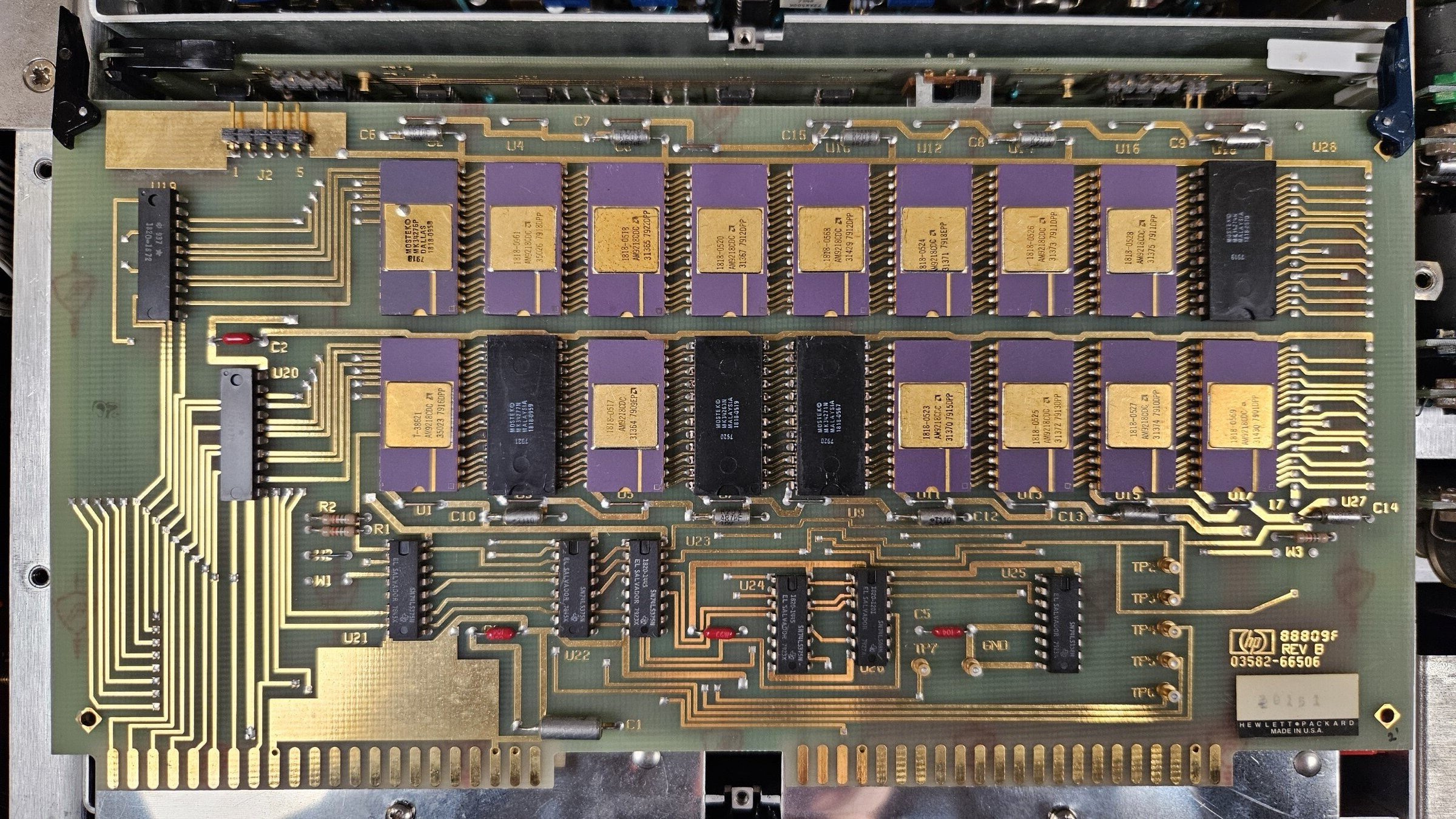
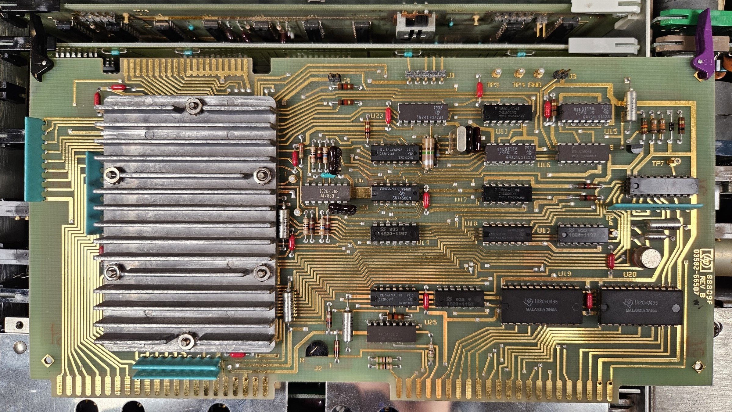
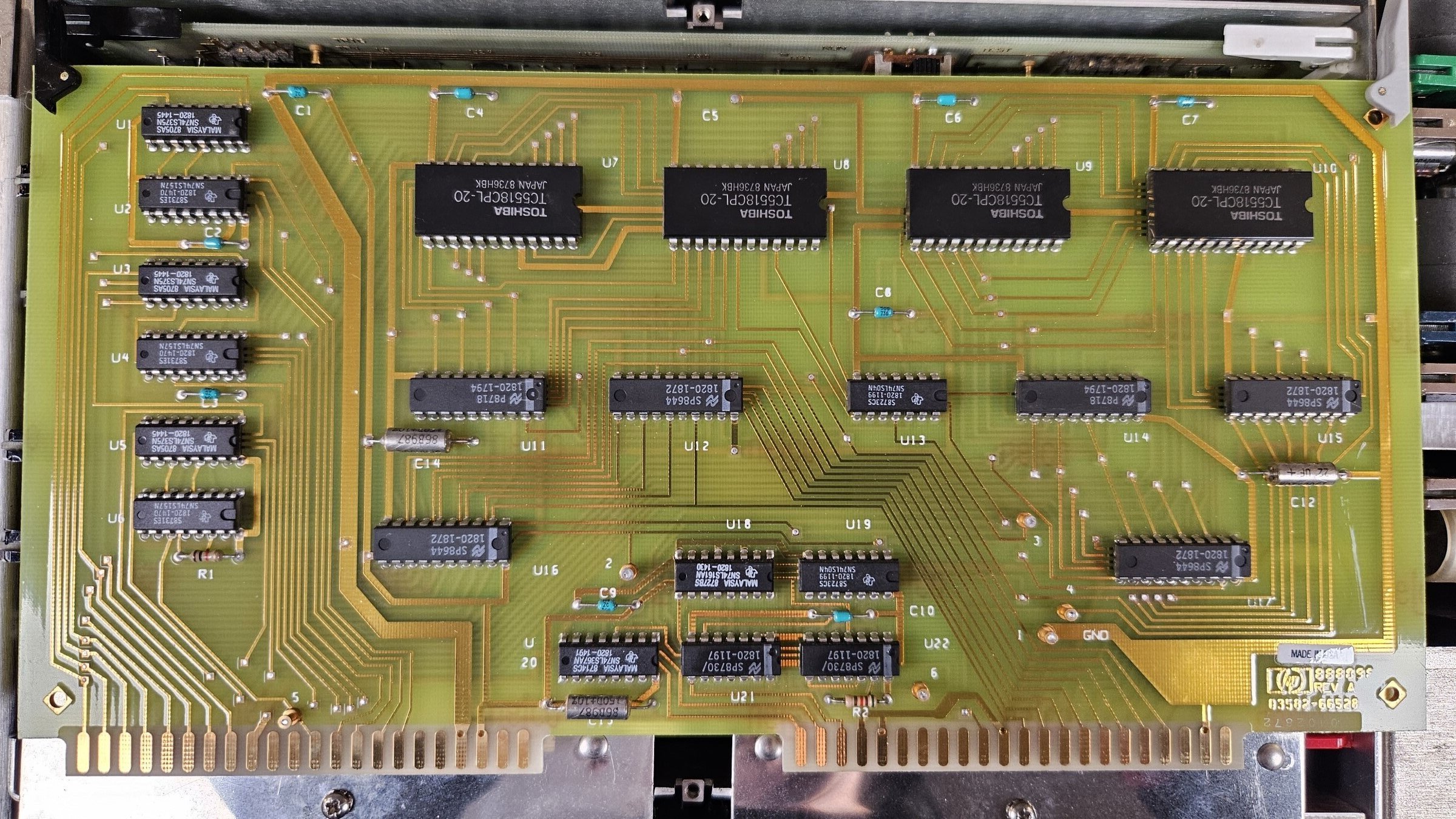
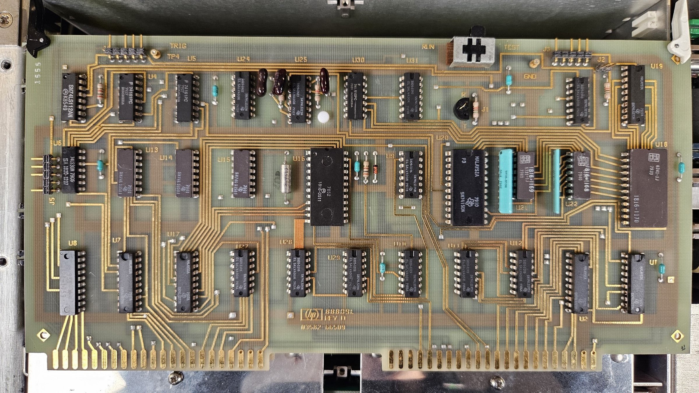
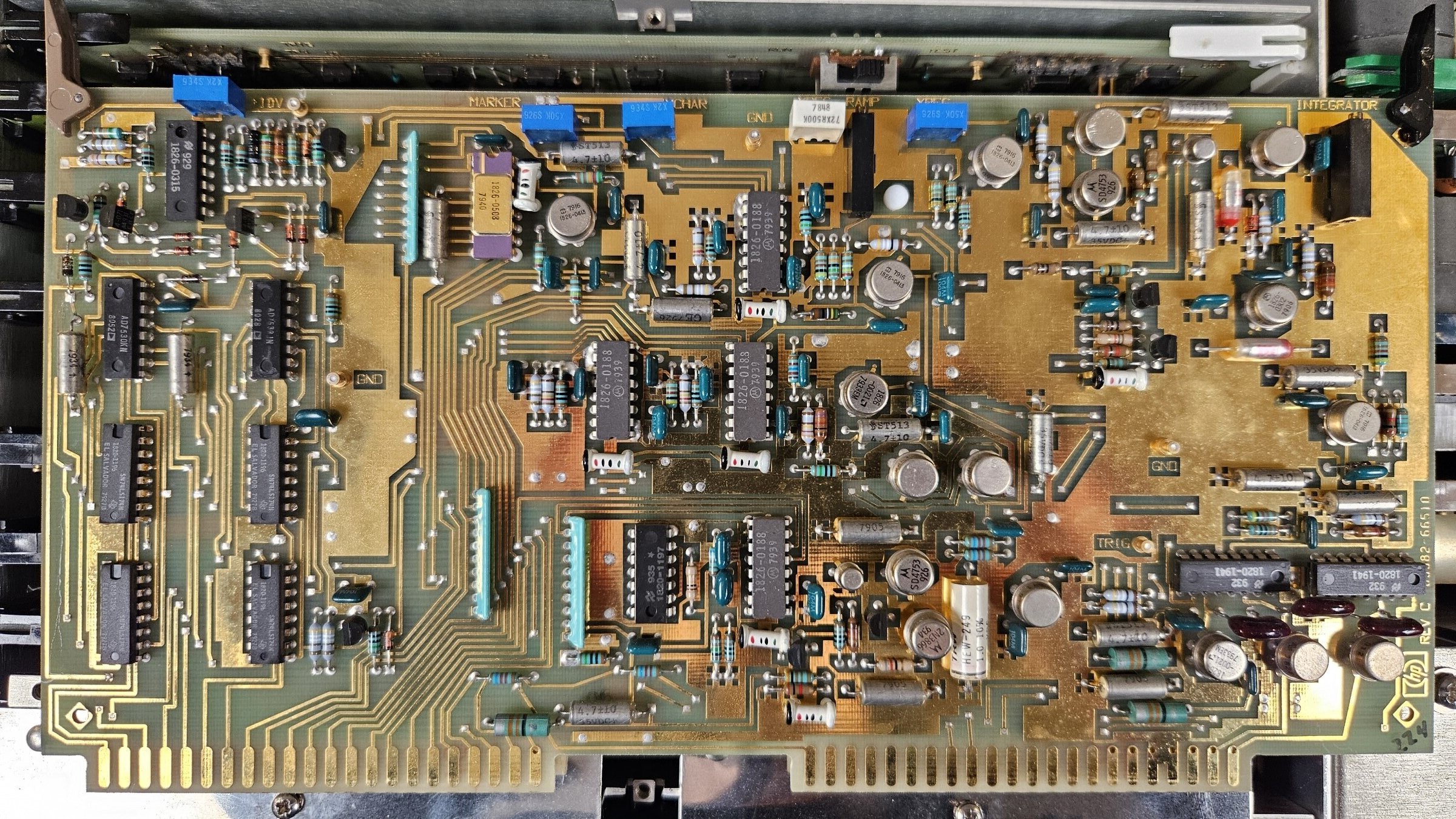
I could not remove all the cards, as the input section and input amplifiers had extra shielding. As the display problems did not indicate problems with the inputs, I decided to not touch these cards. Here is pictures of the cards A6 to A10. A6 is the ROM card, A7 is the processor card, A8 is the RAM card, A9 is the digital display controller and driver and last A10 is the analog display driver.
Power Supply Test of the HP 3582A
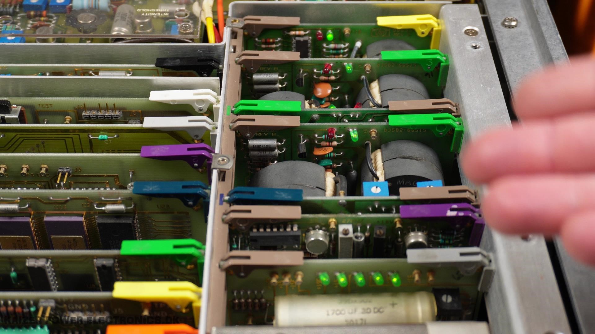
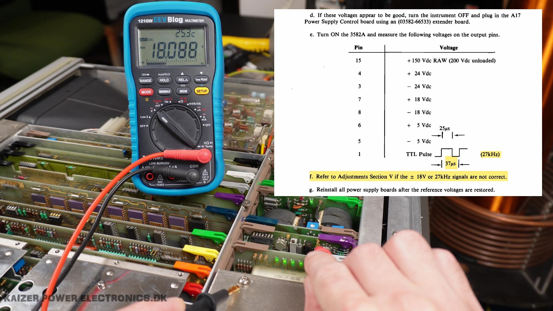
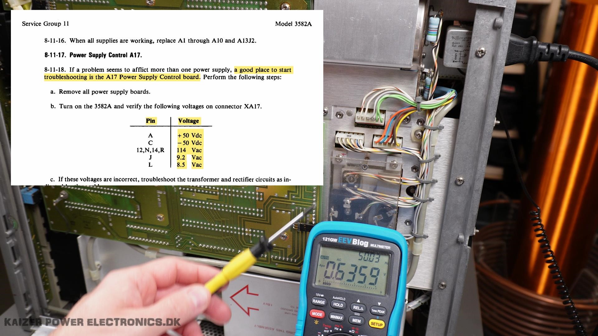
My first suspicion is always the power supply, so luckily this is also some of the first tests according to the manual. A18 is the main power supply card with reference voltages for the other PSU cards and A17 generates a 27 kHz clock for the other PSU cards. Checking the transformer output voltages and raw DC voltages, has to be done from the bottom of the instrument. Here we find the 114 VAC, +50VDC, -50VDC and raw 9VAC for the low voltage sections to be okay.
A18 also show its +5, +15V, -15V rails to be okay and all green LEDs are lit up, some dimmer, but could just be from age of the LED. No red LEDs are lit up indicating overcurrent shutdown. The A17 card has a very stable +18VDC reference voltage and 27 kHz 37us reference signal to the other power supplies. No obvious faults found in the power supply section.
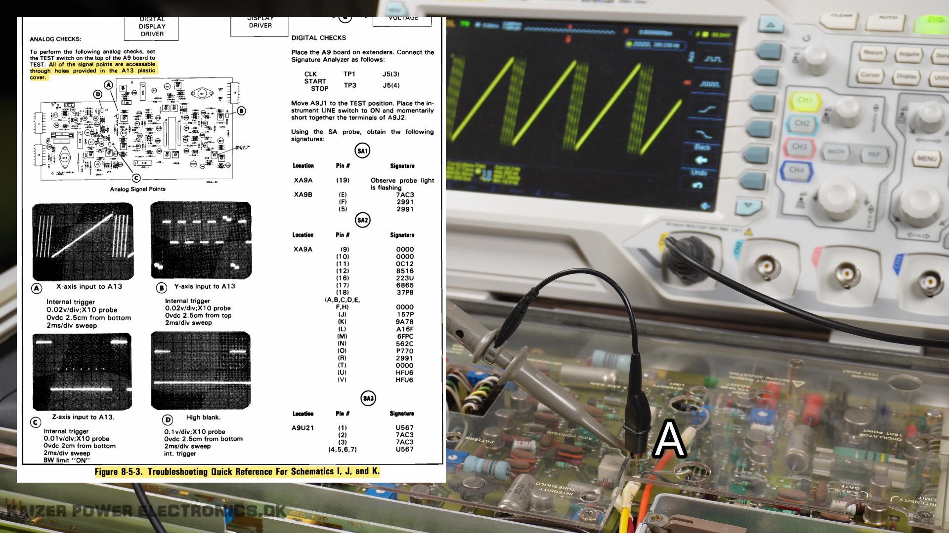
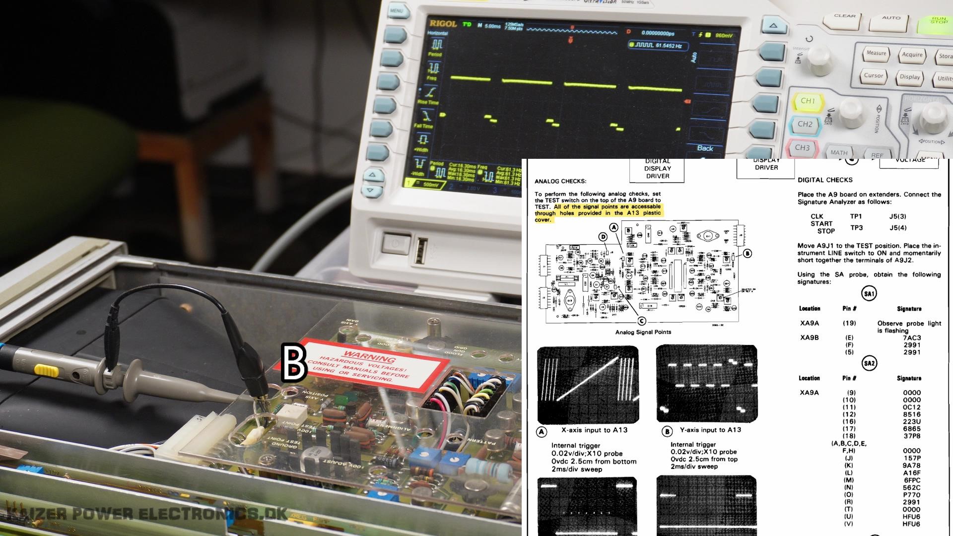
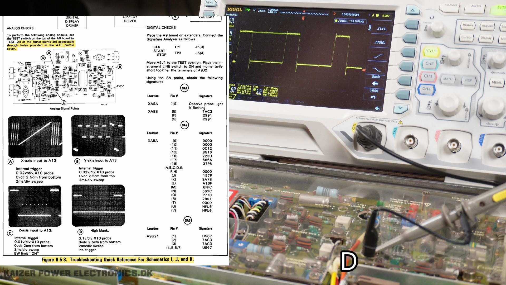
Next step is to work backwards from the problem and see if one of more inputs to the end result, the display, is missing. First up is the A13 board with the XYZ amplifiers. There is 4 marked test points and the service manual has oscillograms to compare the measurements to, very handy and not something you see in a modern instrument. Measure point B does not show up as shown in the manual, a square wave imposed on the waveform seems to be missing. Test point B is the Y-axis input to this A13 board from the A10 board.
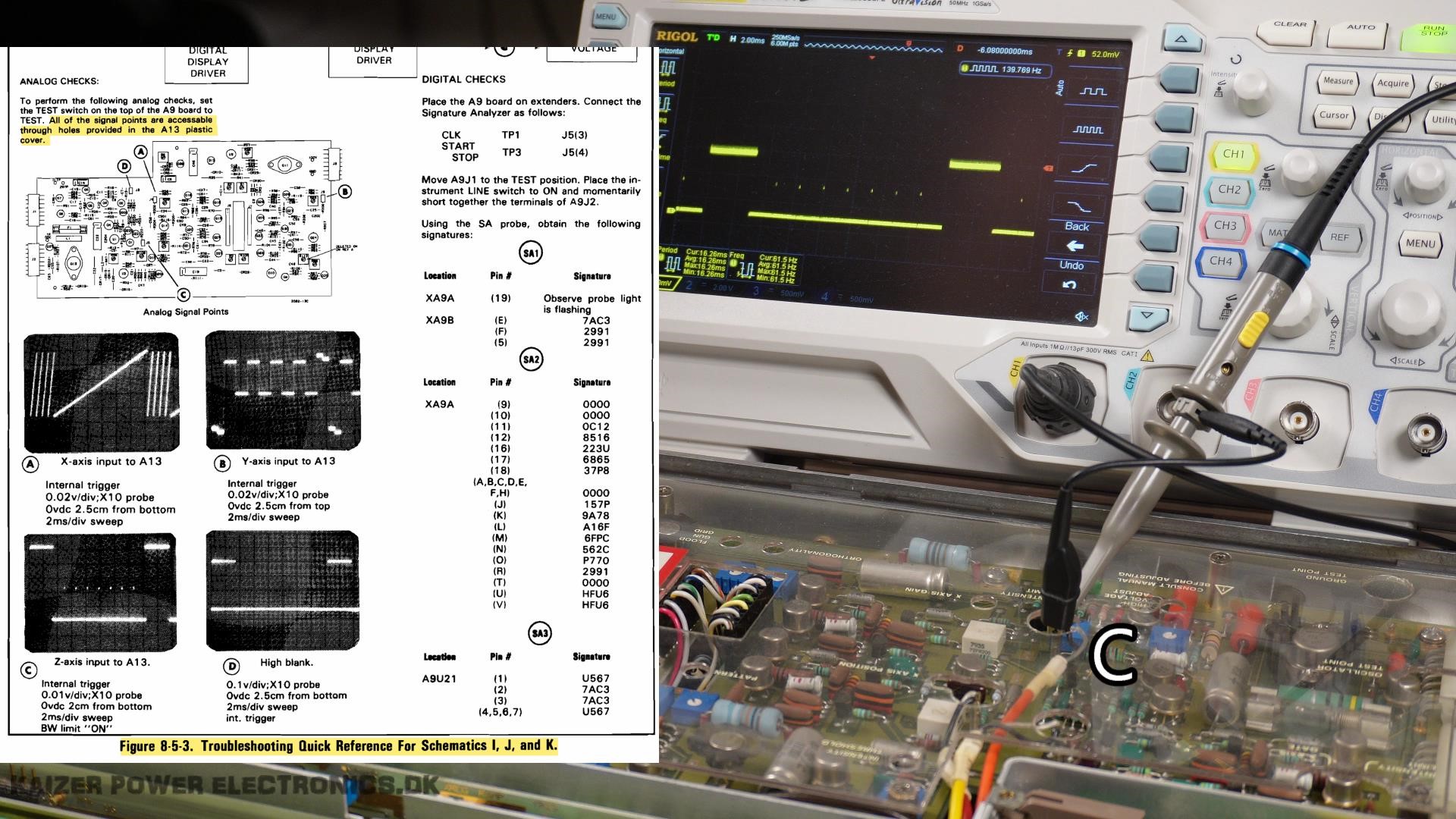
There is 5 test points on the A10 card, 4 of them is the final amplified inputs to the U17 IC. Measurement point A failed to give any readings, a clear sign of U1 DAC and possible U2 buffer is defective, most likely the U1 DAC. From the oscillograms in the manual, it is also hard to determine if the test point E is correct or there is missing square wave imposed in the long high signal part of the waveform, simply due to bad scan of the original manual.
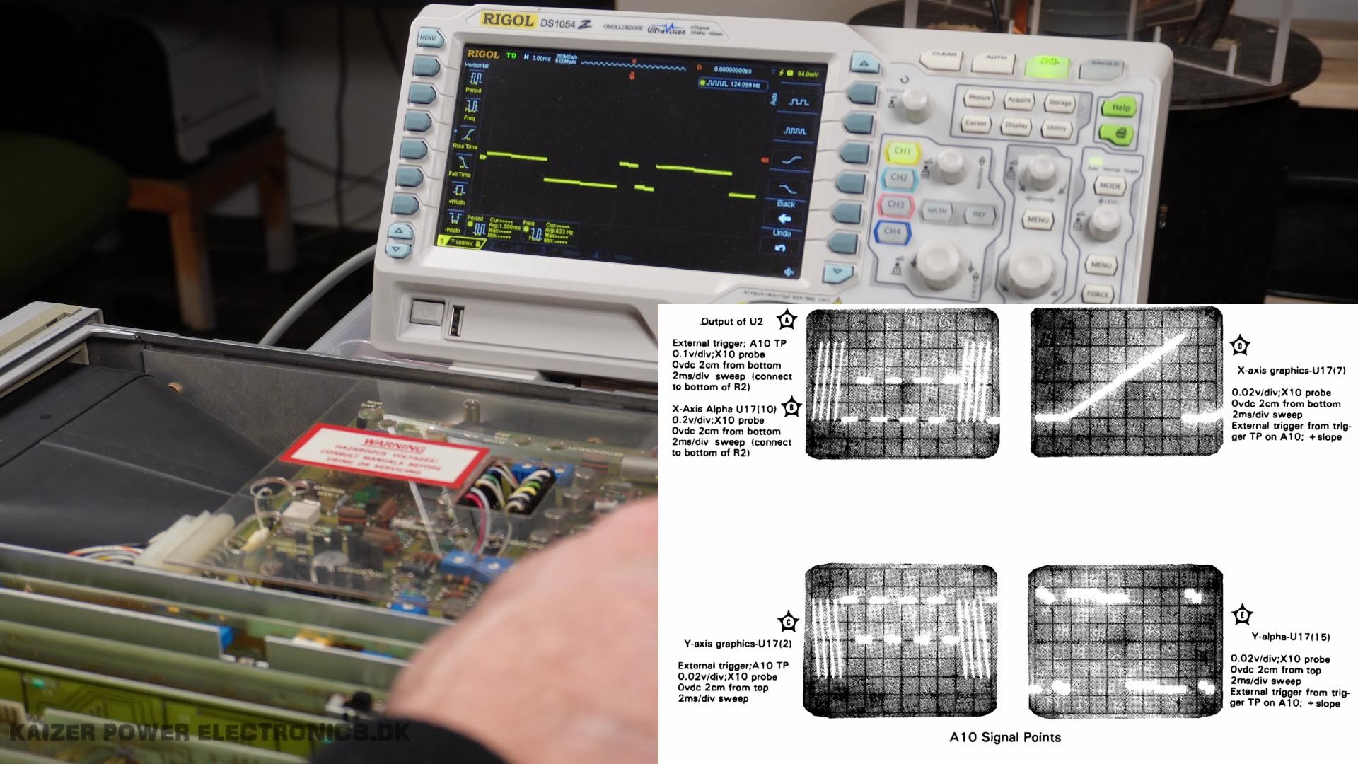
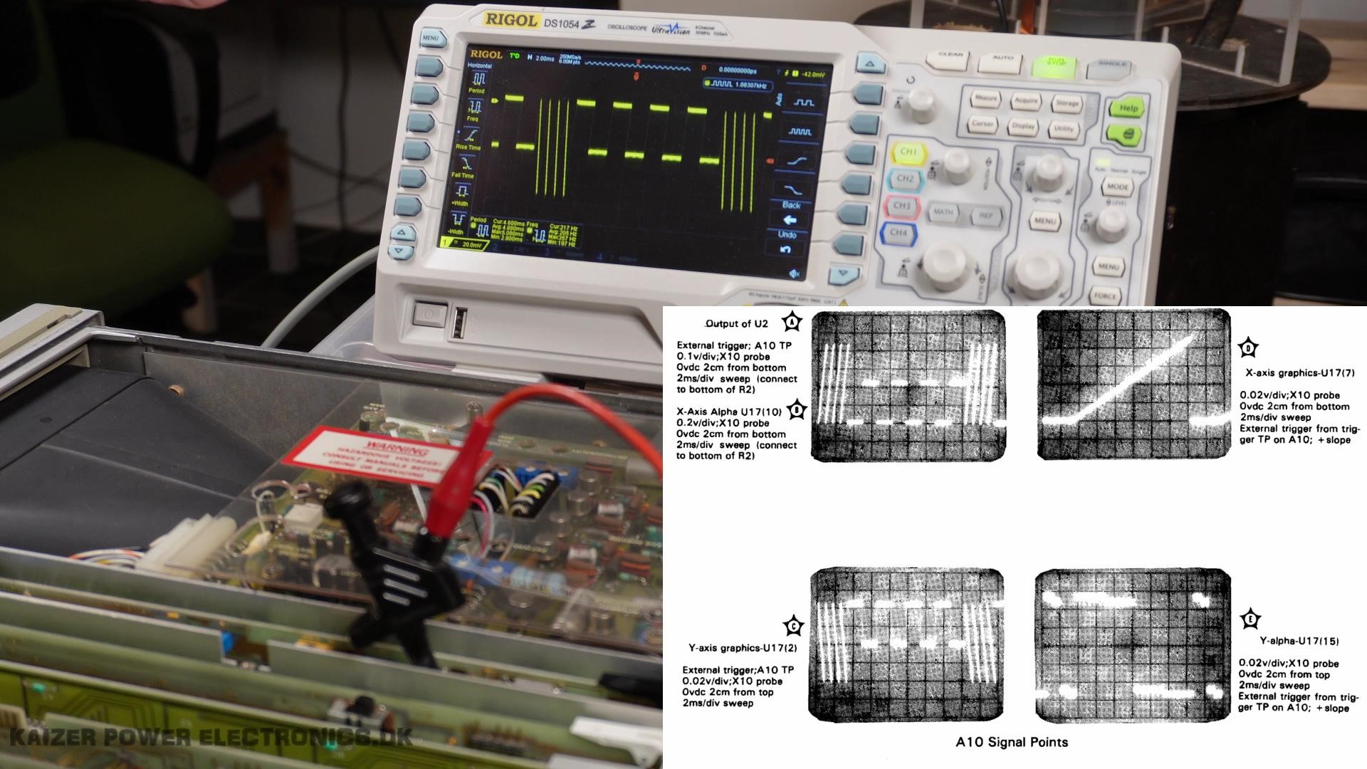
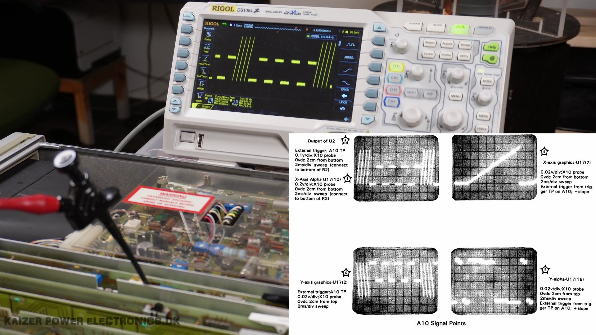
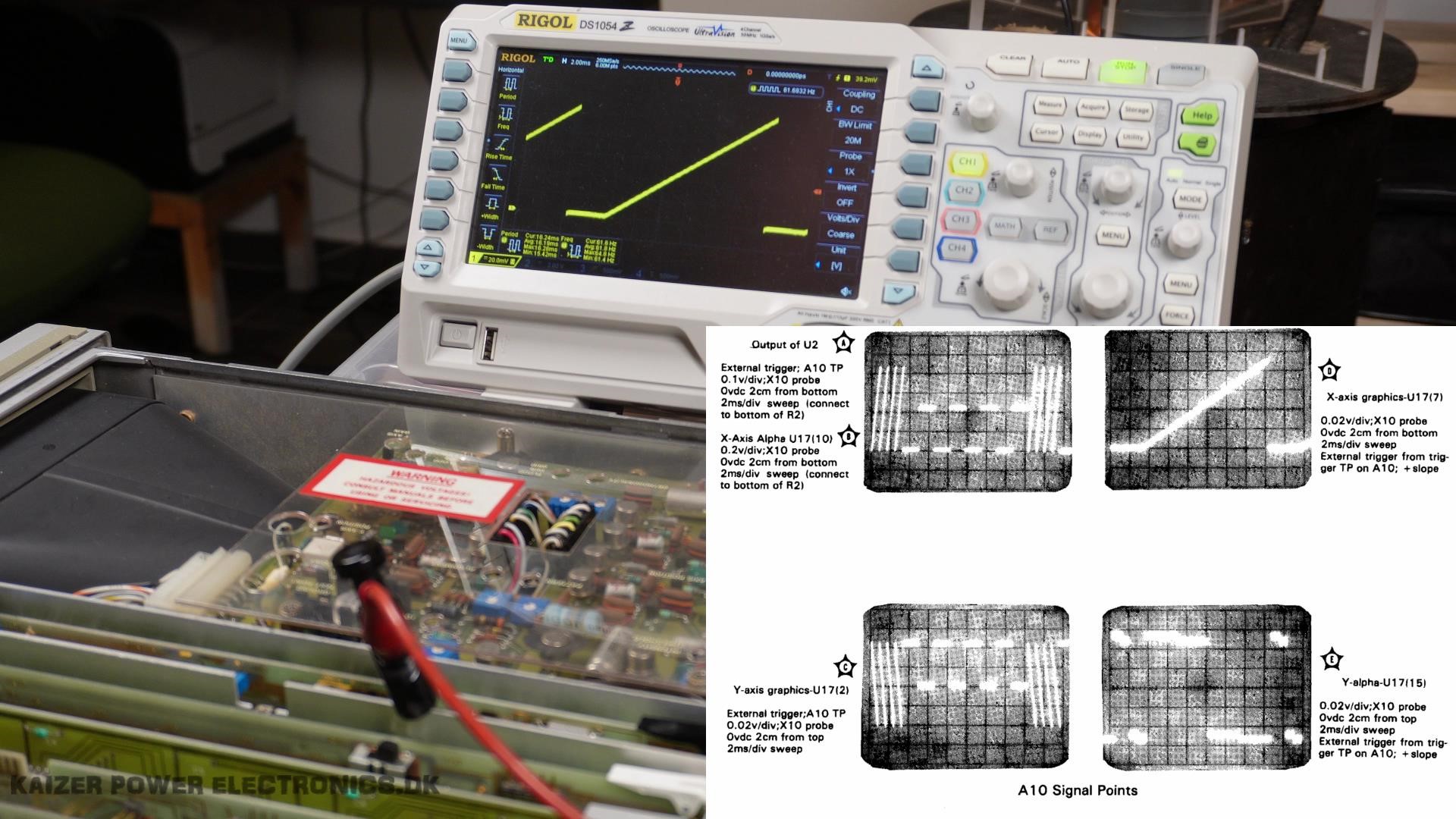
As I did not have the extender boards, to rise the cards up for measurements, I pulled the A10 card out, placed probe and reinserted it. This had to be done for every measurement. When I had finally pinpointed the problem to missing signal from the U1 DAC, I touched the frame, while holding the A10 card with ground clip from oscilloscope still on it. I felt a tingling sensation and immediately knew this could be bad, I felt current running through my fingers, to the card. With a bad feeling, I reinserted the A10 card and now I would not even get a picture on the CRT. I fear I destroyed the card even more and what could have been a 25-40$ repair for a new old DAC, has properly been complicated a lot!
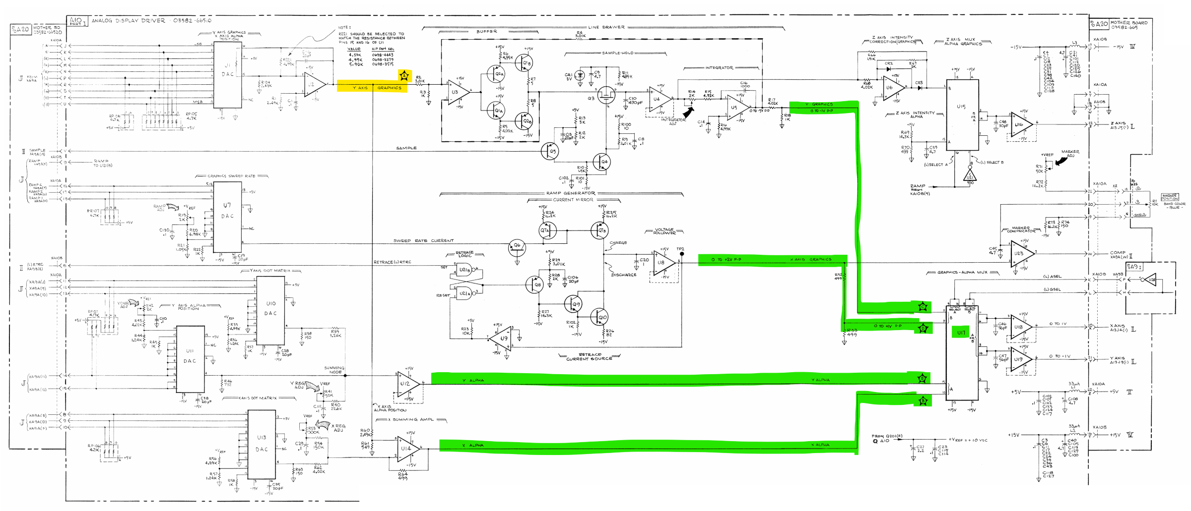
My next step was to find some 22×2 PCB edge connectors and ordered them right away. Now I just need to get them, make some riser/extender PCBs and I can better proper out the A10 card to locate the new faults. In hindsight, I should have started by making these risers and maybe I would not have damaged the card. Lesson learned, make sure to even out the ground potential between oscilloscope and device under test!