The DC bus capacitors are the main energy storage for a DRSSTC inverter. It is important to have the energy needed for high BPS operation of the DRSSTC. Likewise a high enough RMS current capability so we do not damage the capacitors.
A typical 5000 μF / 450 V aluminium electrolytic capacitor will only have a RMS current rating of about 28 A. Therefore it will often be necessary to parallel more capacitors in order to obtain the RMS current capability needed. For aluminium electrolytic capacitors to have higher current rating they must be bigger and thus capacitance and current rating goes up hand in hand.
A large DC link capacitor will have higher voltage and RMS current ratings than electrolytic capacitors. They are designed to avoid series connection. Their much lower ESR prolongs life time and results in lower heat dissipation. The low ESR makes them able to supply high peak currents faster. They can even make snubber capacitors unnecessary if the busbar design is good.
This is chapter 4 of the DRSSTC design guide: DC bus capacitor
Voltage sharing between capacitors in series
With common DC bus voltages at 320, 564 and 800 VDC, it is not always possible to find suitable capacitors with a high enough voltage rating to leave some head room for voltage swings and transients.
Capacitors can be connected in series for a higher voltage rating, but it will divide the capacitance by the number of capacitors in series. So two 450 V 4000 μF capacitors in series will result in a 900 V 2000 μF capacitor. Voltage sharing between the two capacitors depends on their mutual leakage current, below we will see how it can be balanced out.
Used capacitors can have widely different readings for the same type of capacitor. It is necessary to add matched balance resistors to have them share the voltage even between them. Balance resistors will also double as bleeder resistors and add a safety feature that automatically discharges the capacitors.

Balancing Resistors
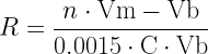
The difference in leakage currents in μA for two capacitors in series at rated temperature can be estimated and used to find a value for balancing resistance for each capacitor as follow:

Where R in MΩ is the balancing resistance, Vm is the maximum voltage you will allow on either capacitor, Vb is the maximum bus voltage across the two capacitors, and C is the capacitance in μF for each capacitor. For three or more capacitors in series use the following where n is the number of capacitors in series [2]
If we have two 200 VDC 6000 μF capacitors in series for a 320 VDC bus voltage, we will allow a maximum of 180 VDC on each.
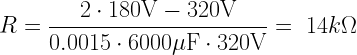
For 320 VDC bus voltage, a 15kΩ 5 Watt resistor across 6000 μF capacitance at 180 VDC will discharge it to 24 VDC in 3 minutes while dissipating 2.16 Watt.

If we have two 350 VDC 4000 μF capacitors in series for a 564 VDC bus voltage, we will allow a maximum of 320 VDC on each.

For 564 VDC bus voltage a 22kΩ 8 Watt resistor across 4000 μF capacitance at 320 VDC will discharge it to 24 VDC in 4 minutes while dissipating 4.65 Watt.

You can use a online capacitor discharge calculator to find the values that suit your safety or power dissipation requirements.
Half-bridge input capacitor values
Voltage divider capacitors in a half-bridge is a matter of losses, there is quite a difference from electrolytic to film capacitors depending on the switching frequency.
The capacitance value needs to be large enough to keep the center point stable, with low ESR and ESL also being important. Under some transient conditions the center point is fluctuating, so it is important to derate the capacitors voltage wise. The center point of the half-bridge capacitive divider drifts either towards the input voltage or the ground. This leads to the saturation of the power transformer and requires the input capacitors to be rated to at least the input voltage, this gives 50% head room.
The above two parts on series connection and balancing resistors apply to this.
Current sharing between capacitors in parallel
Capacitors can be connected in parallel for increased capacitance and ripple-current capability. When connecting capacitors in parallel it is important to design the connecting bus according to the guidelines given in Chapter 2: Busbar and primary circuit.
Path resistance to each capacitor should be equal to assure equal current sharing, as it was described in Chapter 1: Rectifiers. The rectifier closest to the supply would conduct the most current, it is the capacitor closest to the load that will conduct the most current. The 40% current derating rule can also be used for capacitors in parallel to correct for uneven current sharing.

While ripple current divides among the capacitors in proportion to capacitance values for low-frequency ripple, high frequency ripple current divides in inverse proportion to ESR values and path resistance. [2]
This means that parallel capacitors in applications with low frequency load will share the current according to the capacitance of each capacitor in parallel. Whereas a load operating at a high frequency, like a DRSSTC does, the current sharing is up to ESR values and resistance of the busbar and wires in the circuit.
Calculating the ripple current and RMS current
In order to determine how many capacitors we need, so we do not damage them, it is most important to look at the ripple current generated by our inverter.
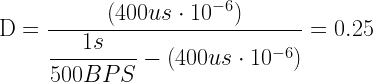
First we need to find the duty cycle and this example uses some very high figures like 400 μs on time and 500 BPS. The costs of filtering capacitors is not that high, so we want to design for long life time. D is the relative duty cycle and is calculated from full square wave period. D = t1 / t2 where t1 is the on part of the period and t2 is the off part.
I will use my own large DRSSTC, Kaizer DRSSTC III as an example. It resonates at 38kHz, have a primary inductance of 33 μH and a bus voltage of 564 VDC.

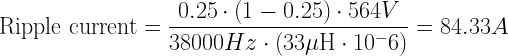
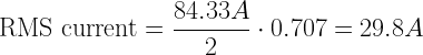
From the datasheet of the Siemens 6000 μF / 350 V B43566 aluminium electrolytic capacitors that I use for the DRSSTC, it can be found that the current rating at 85ºC with frequency factor is 25 A. So I need two capacitors in parallel to handle the RMS current at the worst possible conditions. I used two capacitors in series for the voltage rating to be sufficient, so I have a total rating of 6000 μF / 700 V in the capacitor bank. [3]
DC bus capacitance needed in regard to expected performance of the DRSSTC
In a regular inverter, or resonant inverter the next step would be to calculate the ripple voltage and size the capacitance according to allowed voltage drop. These equations does however not work for a average assumed duty cycle when we draw very large currents in a very short time. There is simply no time for the mains supply to fill the capacitors back up doing a DRSSTC burst, it is first in the off time this will happen. So doing a 200 μs long burst the voltage might drop several 10’s and even up to 100’s of Volt, which can severely hinder the growth of long sparks.
We can instead estimate the energy needed per bang with the help of three key parameters in DRSSTC design, DC bus voltage, primary peak current and on time. All of these are numbers that can be guessed with a certain accuracy as they are coil size dependant and more like design estimates with large margins in reality.
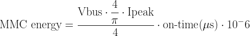
I will again use some numbers from my large DRSSTC mentioned earlier. 564 VDC bus voltage, 2000 Ampere peak current in the primary circuit and 150 μs on-time.
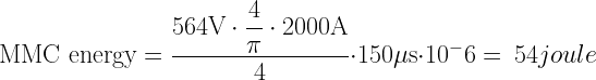
We then calculate the energy stored in the DC bus capacitor bank of 6000 uF at 564 VDC


The ratio between the DC bus capacitor energy and MMC energy should be somewhere between 20 to 50 times more energy stored in the DC bus capacitor. These ratio numbers are based on the normal operation of a DRSSTC. Very long on-times and high BPS does require more energy for the voltage not to sag too much.
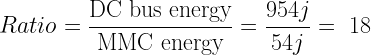
The DC bus capacitor energy is actually in the low end of the suggested ratio, this means that my large DRSSTC will suffer from DC bus voltage sag during long bursts.
Doing a burst we can estimate the voltage drop on the DC bus capacitor by subtracting the MMC energy from the DC bus capacitor energy and calculate the voltage that is left on the capacitor. We can use this approach as we assume the mains do not have time enough to recharge the capacitors doing a burst. First we need to know how much energy is left.

Now we can calculate the voltage drop of 6000 μF charged to 564 VDC dropping from 954 joule charge to 900 joule.
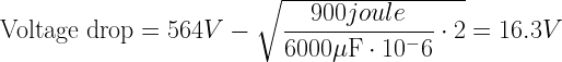
This is just below 3% voltage drop and is acceptable, had I designed for 2500 Ampere primary peak current and 200 μs on-time, the voltage drop would have been just below 5%.
Small vs. large capacitor terminals
If it is not possible to find a datasheet or the current capabilities of a certain capacitor you have at hand, a look at its physical construction can give you a hint about its suited applications.
Long capacitors with small terminals and a large capacity are made for applications needing a very stable voltage but with little or moderate current draw. Short capacitors with large terminals are constructed to conduct higher RMS currents and it must therefore also have a lower ESR.
Capacitance and voltage rating is not everything, judge a capacitor by its physical dimensions and terminal size.


Aluminium electrolytic mounting positions
Aluminium electrolytic capacitors have longer operating lives at lower ambient temperatures so place the capacitors at the coolest place in the DRSSTC.
Ensure that aluminium electrolytic capacitors are away from hot components like power resistors, power transistors, diodes and transformers.
Adequately space components apart for cooling air to circulate. This is especially important when high ripple current or charge/discharge loads are applied.
Mount screw-terminal capacitors upright with terminals up or horizontally with pressure-relief vent plug pointing upwards. This way the least amount of electrolyte will be expelled if the vent operates. Do not mount upside down with terminals down as this may reduce the operating life and could impair the operation of the pressure-relief vent.
Horizontal Mounting of screw terminal aluminium electrolytic capacitors, there are reports that if mounted horizontally, the positive terminal should be above the negative terminal to avoid corrosion. For high ripple current applications of screw terminal aluminium electrolytic capacitors with extended paper, horizontal mounting shortens the lifetime.
With heating from ripple current the electrolyte in such capacitors may bleed from the winding, and puddle along the side of the can where there is no paper to wick it back into the winding. If the ripple current is low (less than half of rated 85 ºC current), this is not an issue. But if the ripple current is high, the effect is accelerated due both to the increasing temperature driving the electrolyte out faster and to the drying of the wet paper where it is crushed into the can bottom. The drying of the paper can thermally insulate the element causing it to get hotter and the can bottom to get cooler. This can actually turn into a thermal runaway condition that can greatly reduce the capacitor lifetime, sometimes by as much as 90%. [2]
Aluminium electrolytic capacitors vs film capacitors
Comparison table of different properties for Electrolytic aluminium capacitors and film capacitors. [1]
| \ | Aluminium electrolytic capacitor | Film capacitor |
| Capacitance | High energy density, 3 times higher than film | Low |
| Voltage rating | Maximum 550 VDC | Up to 1500 VDC for DC link capacitors. |
| Ripple current at 85ºC | 50% of film | 200% of electrolytic |
| Polarity | Must be connected correct with + and – | Non polar |
| ESR mΩ | Typical 10-15 times higher than film | Typical less than 2 mΩ |
| ESL | About the same for both types | About the same for both types |
| Overvoltage capabilities | 50V surge | 1.5 times rating for 10 seconds |
| Max operating temp. at full ripple | 105ºC | 85ºC |
| Power dissipation | Higher ESR means more heat | Lower ESR means less heat |
| Self healing | No | Most types can self heal |
| Failure mode | Rupture, explosion, short circuit | Fail open circuit |
| Cost per Joule | 0.05 – 0.1$ | 0.2 – 0.5$ |
| Cost per Ampere | 3$ | 1$ |
A word on physical dimensions of capacitors for either DC link or MMC
As demonstrated by El-Husseini, Venet, Rojat and Joubert in their article “Thermal Simulation for Geometric Optimization of Metallized Polypropylene Film Capacitors”, the physical geometry of a capacitor can have an impact on capacitor temperature, power loss and life. They demonstrated that for the same electrical stress, taller capacitors experienced higher temperature and losses than shorter capacitors.
As stated in their article, in taller capacitors, the current must travel a longer distance through the very thin metal films, thus the total I²R losses are higher compared to a short capacitor. The authors demonstrated that the total power loss in the capacitor is proportional to Equivalent Series Resistance (ESR) and to the square of the true rms current.
ESR represents the eddy current and dielectric losses, which are affected by both frequency and current. If capacitor current is elevated, power loss increases. Likewise, power loss in a metallized film capacitor increases if the frequency of the current increases. Thus, harmonic current flowing in a metallized film capacitor, the power loss will be higher than if pure sinusoidal current were to flow. [4]
As the following equation shows, it is the RMS current flowing through a capacitor that is the most vital parameter in temperature rise and too high temperatures lowers life time dramatically.

Cooling of capacitors by forced air can be a solution to get a longer life time. Approximately 2/3 generated heat rise moves out axial and 1/3 radial. So it is most important to cool a capacitor at its terminals as it does not radiate the heat evenly from all over its surface.
Some capacitors have a metal mounting stud in the opposite end of the terminals, these are meant for installation in heat sinks or other material that can lead the heat away. Be aware that the metal can and stud might not be isolated from the negative terminal, depends on manufacturer and capacitor type.
The thermal resistance (Rth) from case to ambient is given for still air in most datasheets, so if forced air cooling is used the thermal resistance can be de-rated. Some manufacturers supply equations to calculate a exact thermal resistance in regard to capacitor surface and forced air speed velocity.
DC bus capacitor conclusion
Size the bus capacitance to have at least 20 to 50 times the energy in Joules as the MMC / tank capacitor of the DRSSTC, this is to ensure we have enough energy available for long spark bursts.
Always have a good head room on the voltage rating, this is by far most important for aluminium electrolytic capacitors. The bus supply voltage should not be more than 75% to 80% of the rated voltage of the bus capacitor.
Use film DC link capacitors if it is possible to find them. They are superior in surge rating, current rating and low ESR. Aluminium electrolytic capacitors is by far the most normal choice due to their low cost. When using electrolytics be sure to get some with as low ESR as possible and high RMS current capability.
Be sure to have enough RMS current capability in your DC bus capacitors, this is the number one reason for cooked and damaged capacitors. Add as many capacitors in parallel as needed.
Try to find capacitors that are short and with large terminals. These will dissipate less heat due to the distance the ESR is spread over. Large terminals are better to dissipate heat and could mean its rated for high currents.
Mount Aluminium electrolytic capacitor in a upright position for the lowest heat dissipation and longest life time. If they are mounted horizontal, have the venting hole pointing up to ensure only a minimum of electrolytic liquid will get sprayed out doing a failure.
Forced air cooling is a good way of prolonging Aluminium electrolytic capacitor life time when they are to conduct large ripple currents. For both aluminium electrolytic and film capacitors it is important to stay below their temperature rating for a long life time.
All design choices for DC bus capacitors is between cost and life time. Capacitors will degrade over time, it is just a matter of how fast, depending on how much head room we design with. Aluminium electrolytic capacitors does however degrade much faster than film capacitors.
Published on: Feb 16, 2015. Updated on: November 4, 2021
References
[1] Cornell Dubilier, “Advances in Capacitors and Ultracapacitors for Power Electronics – Industrial Session 1.3”, Applied Power Energy Conference (APEC), March 2013.
[2] CDM Cornell Dubilier, “Aluminum Electrolytic Capacitor Application Guide”, http://www.cde.com/resources/catalogs/AEappGUIDE.pdf
[3] Michael Salcone and Joe Bond, “Selecting Film Bus Link Capacitors For High Performance Inverter Applications”, https://www.kalbeck.com/asset/630/Whitepaper%20SalconeBond.pdf
[4] M.H. El-Husseini, Pacal Venet, Gerard Rojat and Charles Joubert, “Thermal Simulation for Geometric Optimization of Metallized Polypropylene Film Capacitors”, IEEE Trans. Industry Appl, vol. 38, pp713-718, May/June 2002.
[5] Ajay Hari, Senior Applications Engineer and Robert Oppen, Design Manager. “Average Current Limit Balances Center Point of Half-Bridge Input Caps”, Literature Number: SNVA607, 2011.
Hey Mads!
I have a question about the blancing / bleeder resistors. I read that you (apart from the safety aspect) could also improve the shifting behavior of your bridge. We are a bit uncertain about the sizing. We feed with 560 V DC and have a 3 mF bus capacitor. Would it also be enough to use 2 of these resistors
https://www.mouser.de/ProductDetail/ARCOL-Ohmite/HS100-4K7-J?qs=bvCpHSZmQjmYL9Bl9GhK7g%3D%3D
in series resistors? Thus, we would have about a resistance of 9.4 kOhm and a converted power in the resistance of about 33 W, which should probably not be a problem for these resistors.
Kind regards,
Michael
Hi Michael K.
That seems reasonable to use, as long as you do not break the voltage specifications of the resistors. Those metal housing power resistors can easily flash-over compared to a old school ceramic power resistor. Mounted on the same heat sink, this problem can get even worse.
Kind regards
Mads
Hello,
I think i found a small mistake in your calculations for the voltage drop. The result is correct, but you subtracted the remaining voltage from the 954 joules of energy instead of the 564V of DC-Bus voltage.
I noticed this mistake because i am writing a scientific paper about DRSSTCs for my final exam. Thank you very much for providing your DRSSTC design guide. It is a great resource for my scientific paper 🙂
Greetings,
Phoenix
Hi Phoenix
Thank you for catching that typing error, its easy to get it mixed up when writing the equations in latex in the wordpress editor. *cough* copy/paste *cough* 🙂
Kind regards
Mads
What does the 1/pi factor represent in your MMC energy calculation? I was thinking the bus current would approximately be a fully rectified sinusoid, so we could use the RMS current to calculate the power.
Energy per bang = Vbus*(Ipeak/sqrt(2))*Ton
Thanks again for the great guide!
Is it acceptable to use 10 pcs of HITANO 470 uF / 400 V electrolytic capacitors (see datasheet) in parallel, i.e. 4000 uF / 400 V in total for full-bridge rectifier for DRSSTC with 2 pieces IGBT FGA60N65SMD i.e. half-bridge?
When measuring one piece, my meter shows a resistance of 0.35 Ohm, i. e. 10 pieces would have 0.035 Ohm. Does that mean at 200 A voltage drop 7 V?
Thanks in advance Stanislav
Hi Stanislav
Yes you can use parallel connected DC bus capacitance. You just have to make sure that they are as close as possible to the IGBTs and that the current paths have equal resistance/impedance. If you connect them with difference length wires, the capacitors with the lowest impedance will supply the most current to the load. Differences in capacitance also matters, the highest capacitance will supply the most current as well.
Kind regards
Mads