This article and video focuses on full mains power startup, secondary coil terminations and connections, adding a new soft start module to the mains input for dealing with high inrush current and blowing the full bridge of IGBTs up completely.
This is the 5th article / video in the series of designing and building a DRSSTC Tesla coil from scratch, with focus on being easy and cheap, for you to replicate. You can find the previous information in these articles:
- Designing A Complete DRSSTC Tesla Coil In 10 Minutes
- Building the 10 Minute DRSSTC Part 1: Finding the Components
- Building the 10 Minute DRSSTC Part 2: Construction and Assembly
- Testing the 10 Minute DRSSTC Part 1: UD2.9 Driver and DC Bus Capacitors
DRSSTC Full-bridge PCB failure
The issues I encountered during this part of the building and testing is also being discussed at High Voltage Forum: https://highvoltageforum.net/index.php?topic=3623.msg26734#msg26734. This is setting me back to either try to fix the full bridge PCB or build new full bridge PCBs for TO247 devices or just move on to IGBT bricks instead.
I should have:
– Tested my IGBTs before soldering the bridge PCB
– Tested more with just driver and bridge, no high voltage
– Used a variac for low voltage testing of the complete system
The coil powered up fine, driver in shutdown state until interrupter signal comes.
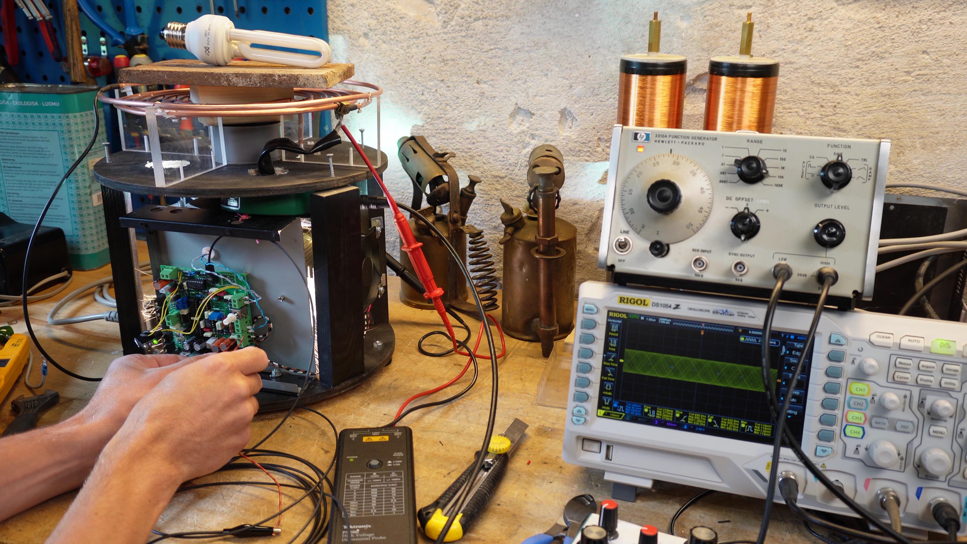
Then nothing happens, no oscillation, so here is things I tried:
– Change polarity on GDT jumpers on the driver
– Change polarity on feedback CT by switching leads around in terminal
– Reduce CT ratio from 1:1000 to 1:200
I then decided to try startup oscillation with a signal generator set at resonant frequency (270 kHz) and inject that shortly by hand to see if that could get it running. But I got punished instead. DC bus at 320 VDC and interrupter set at 120 BPS and very low on-time (I hoped that was enough to save me in failure cases)
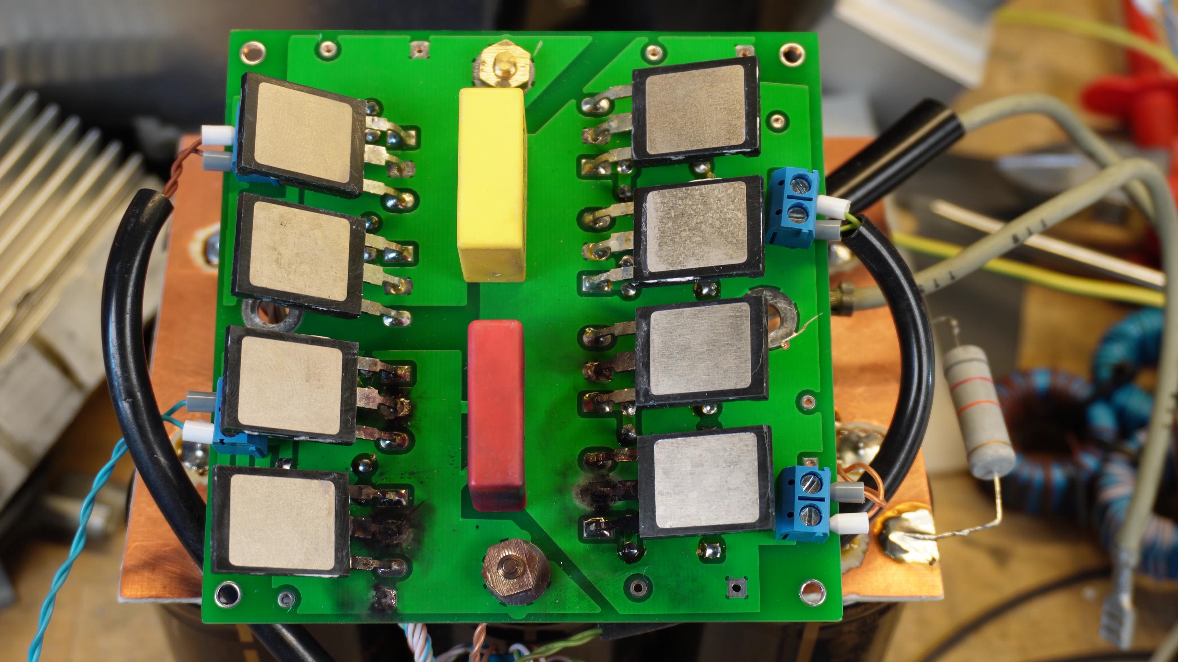
Inspecting the burned PCB shows that Q5,6,7 and 8 is now with black scorch marks, funnily enough the IGBTs seems fine, its the traces of the PCB that has been blown out. It seems that all collectors melted the tracks away. The pads also only have these 4 small bridges to the plane, not full connections (for easier soldering).
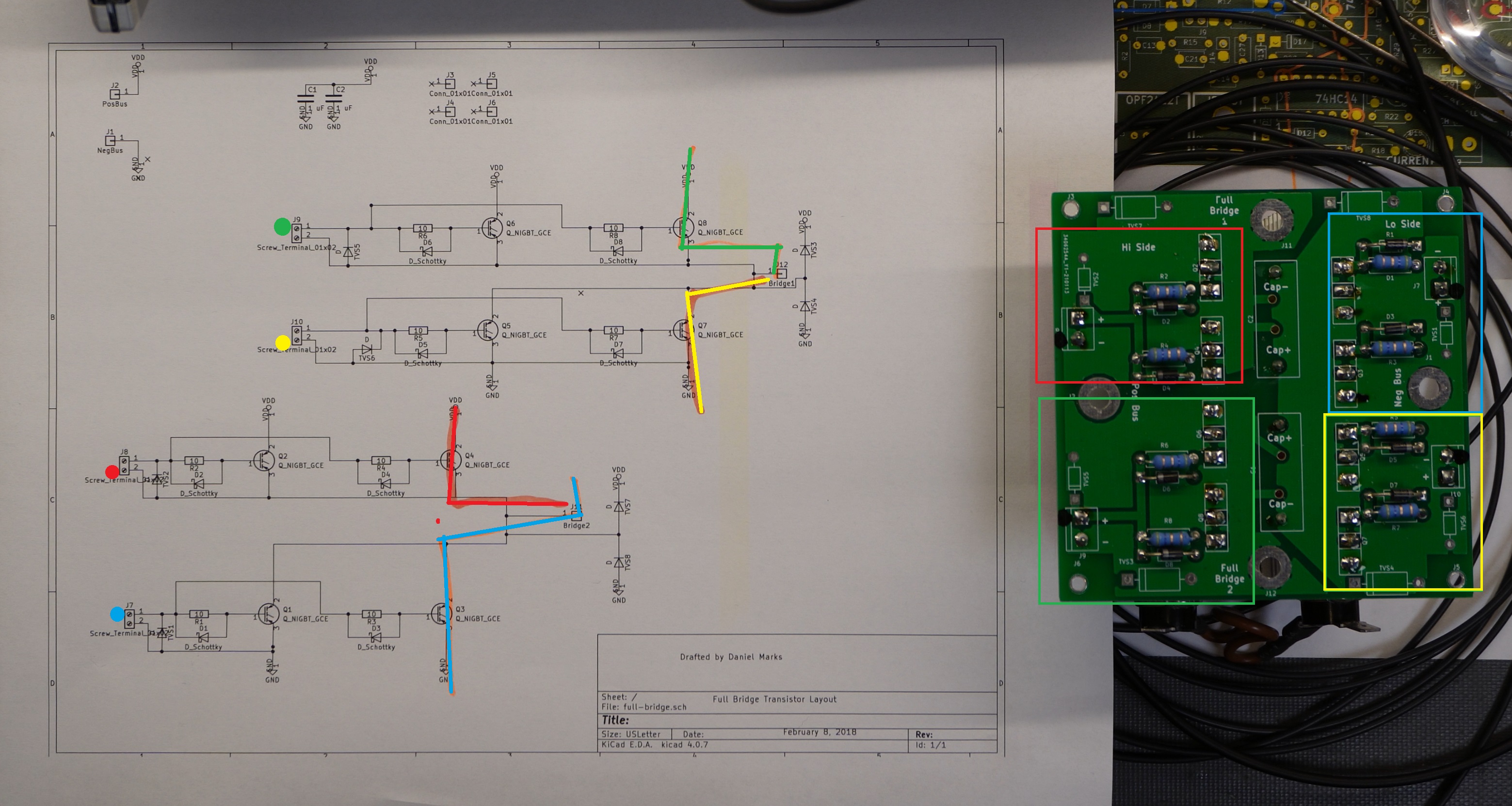
I double checked wiring, GDT winding, schematics and bridge PCBs to look for errors that could result in this total short circuit from what seems like wrong phase of driving.
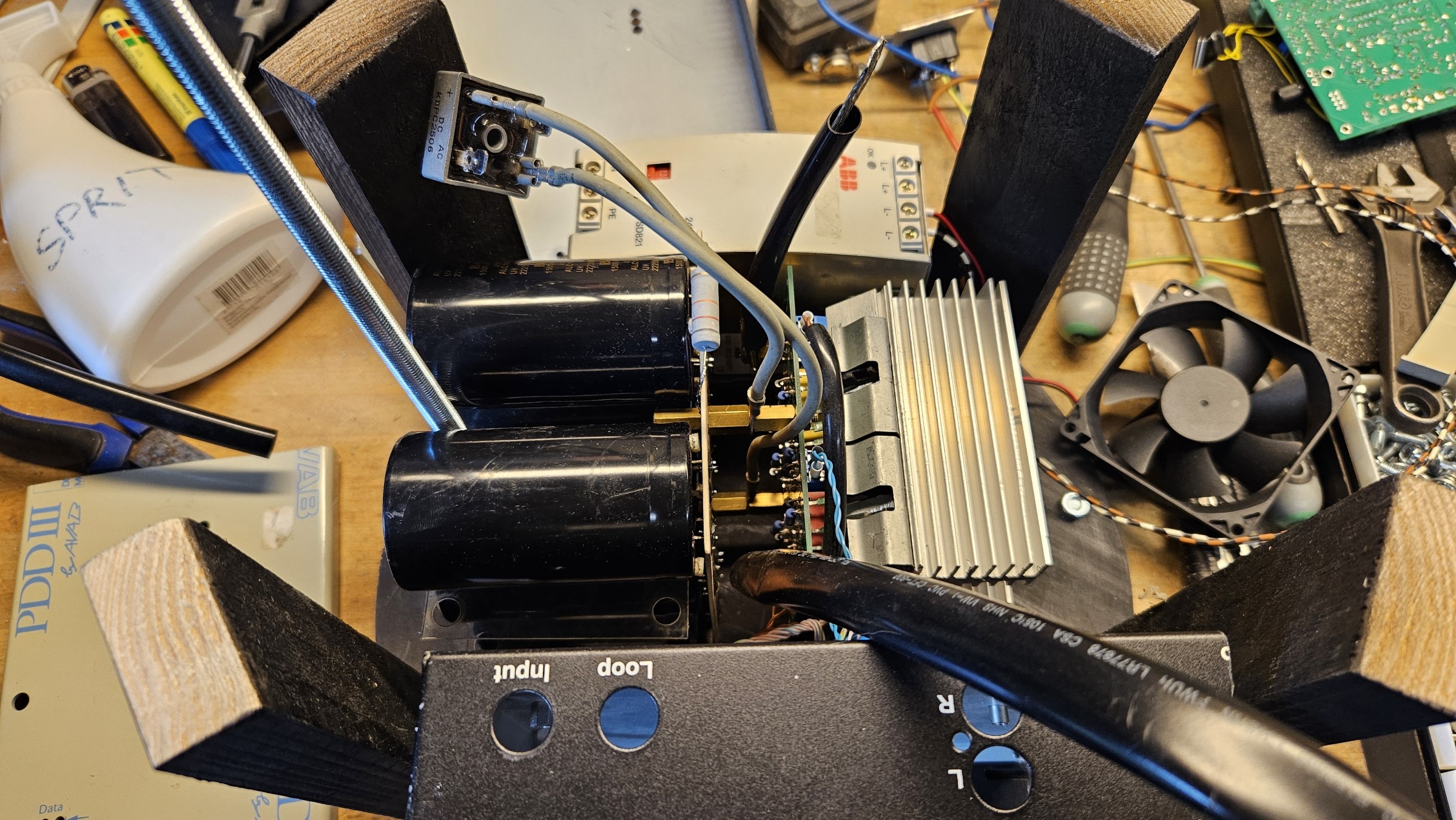
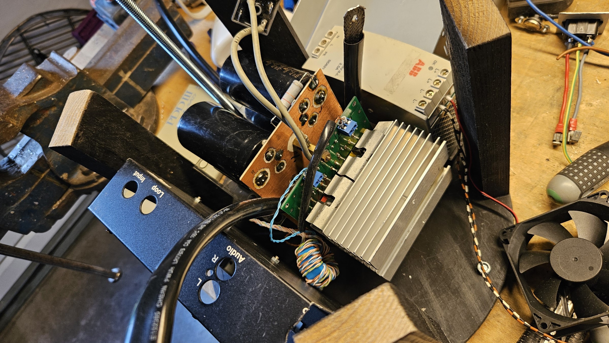
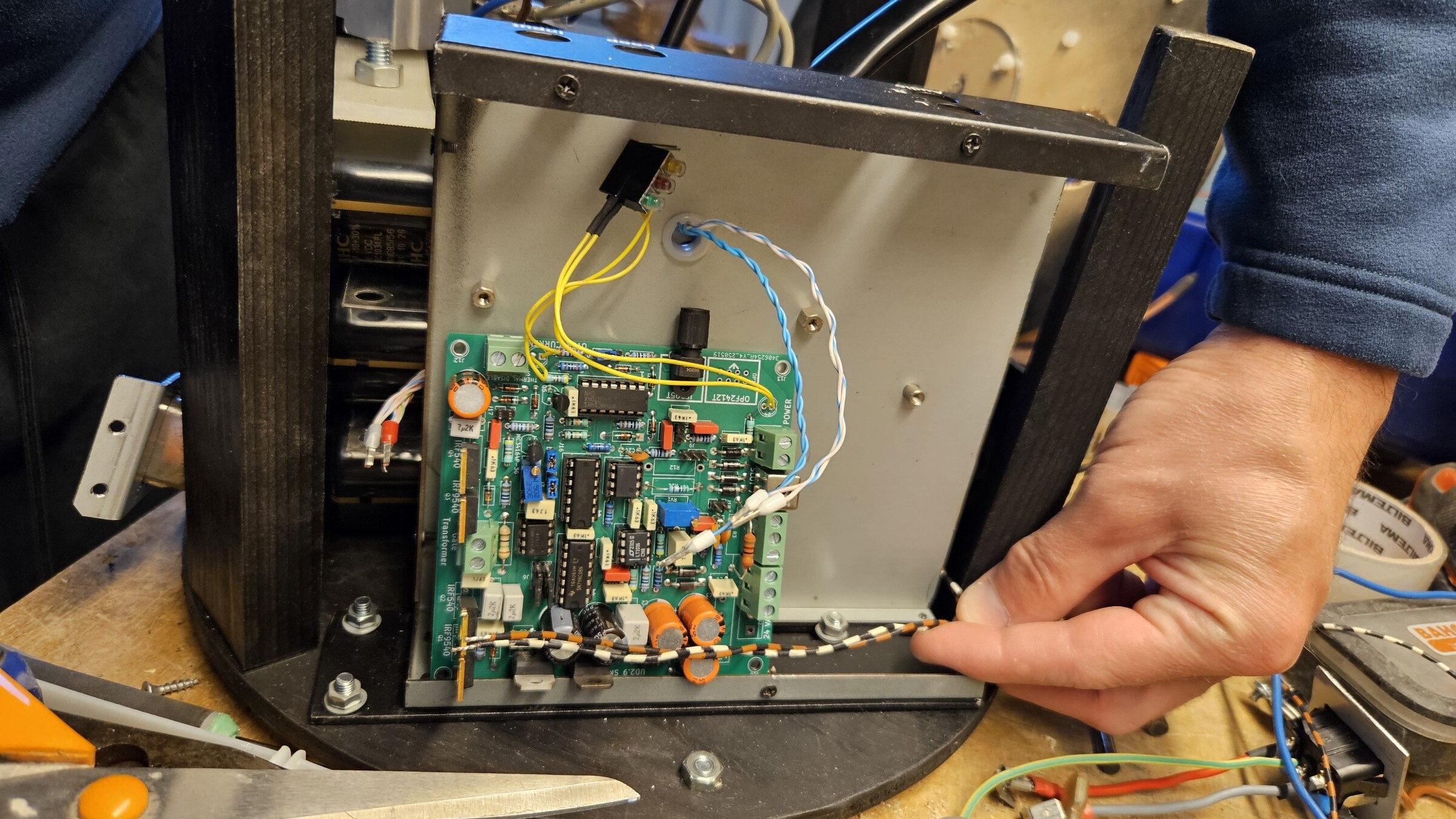
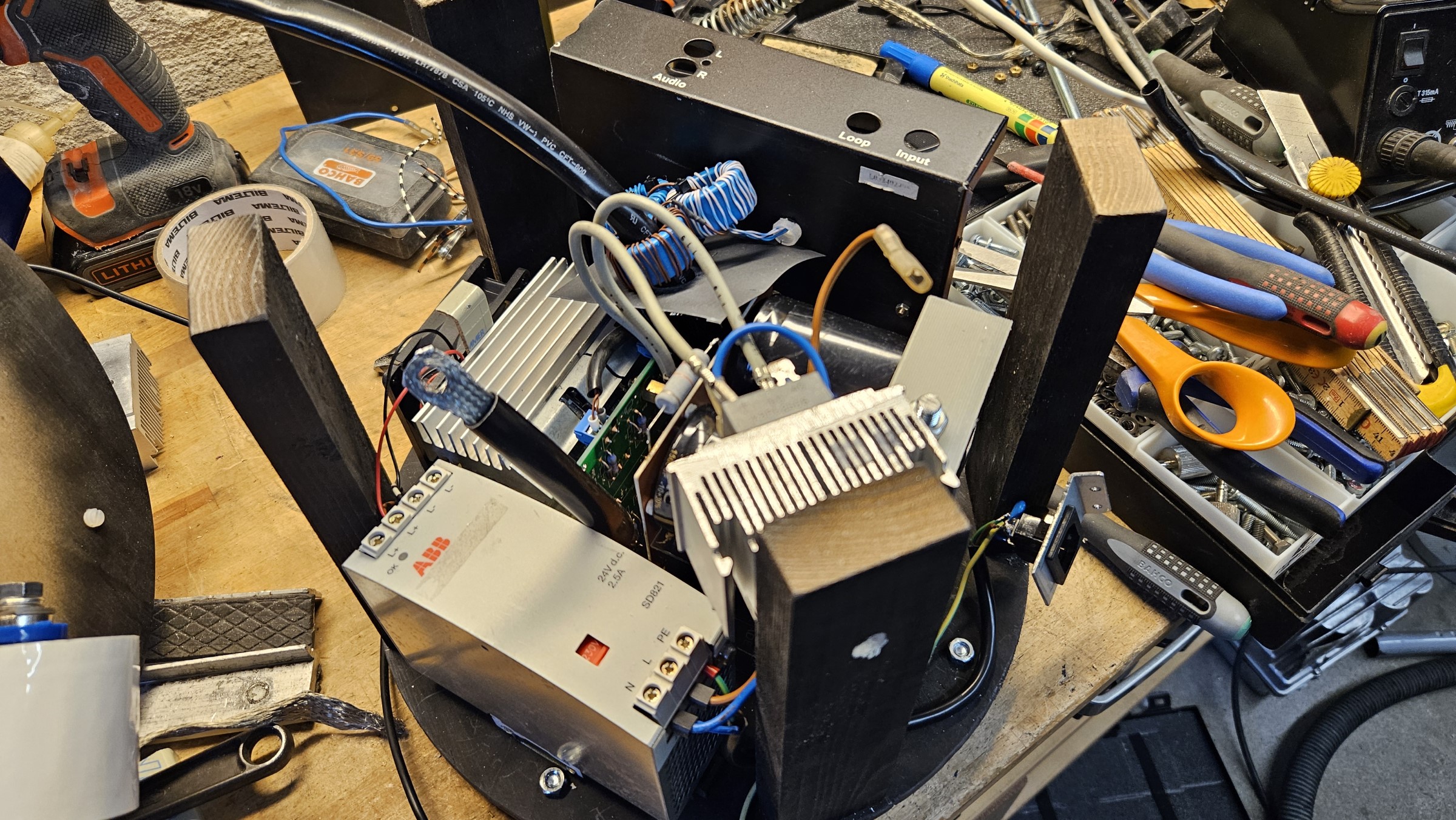
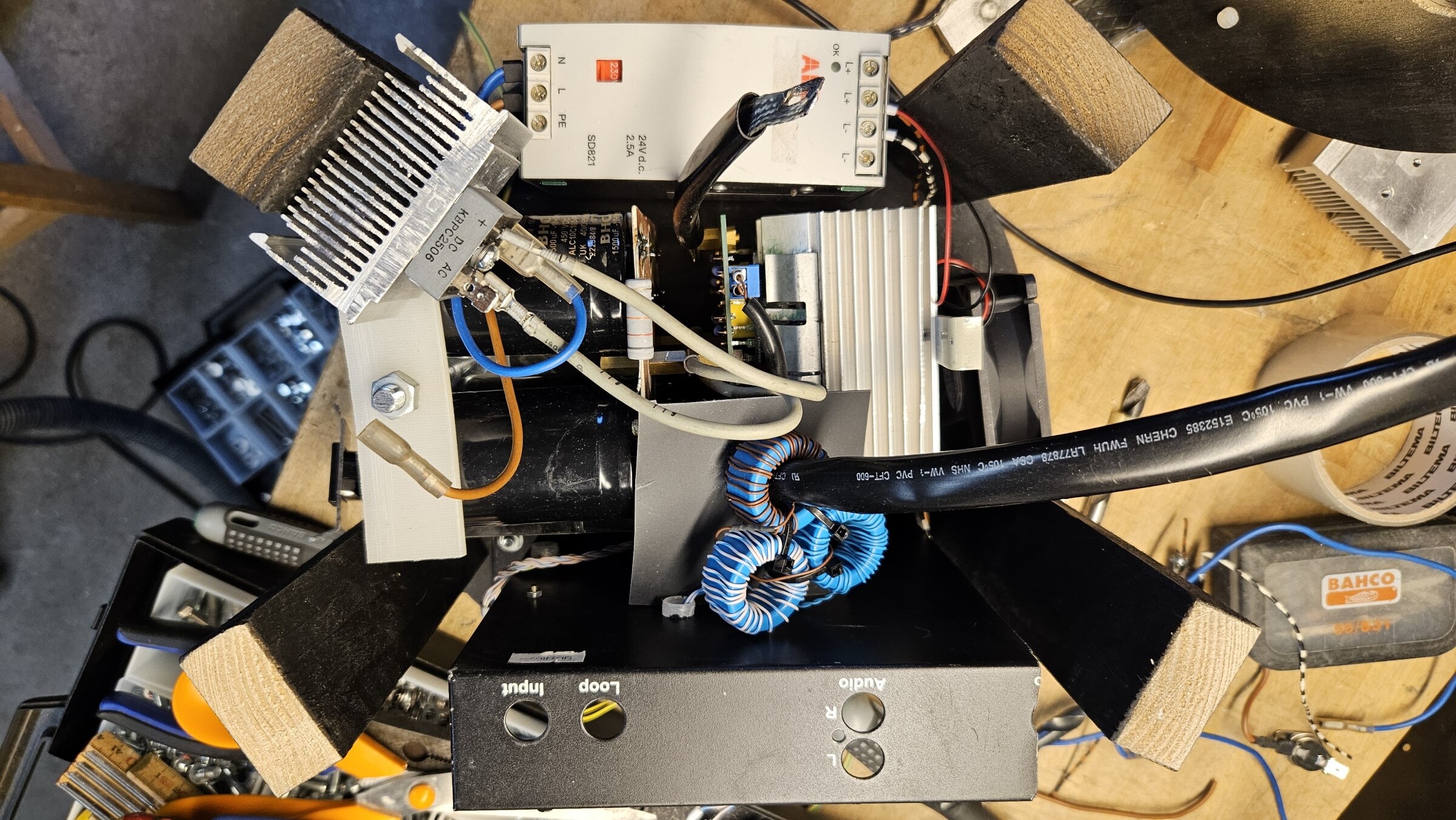
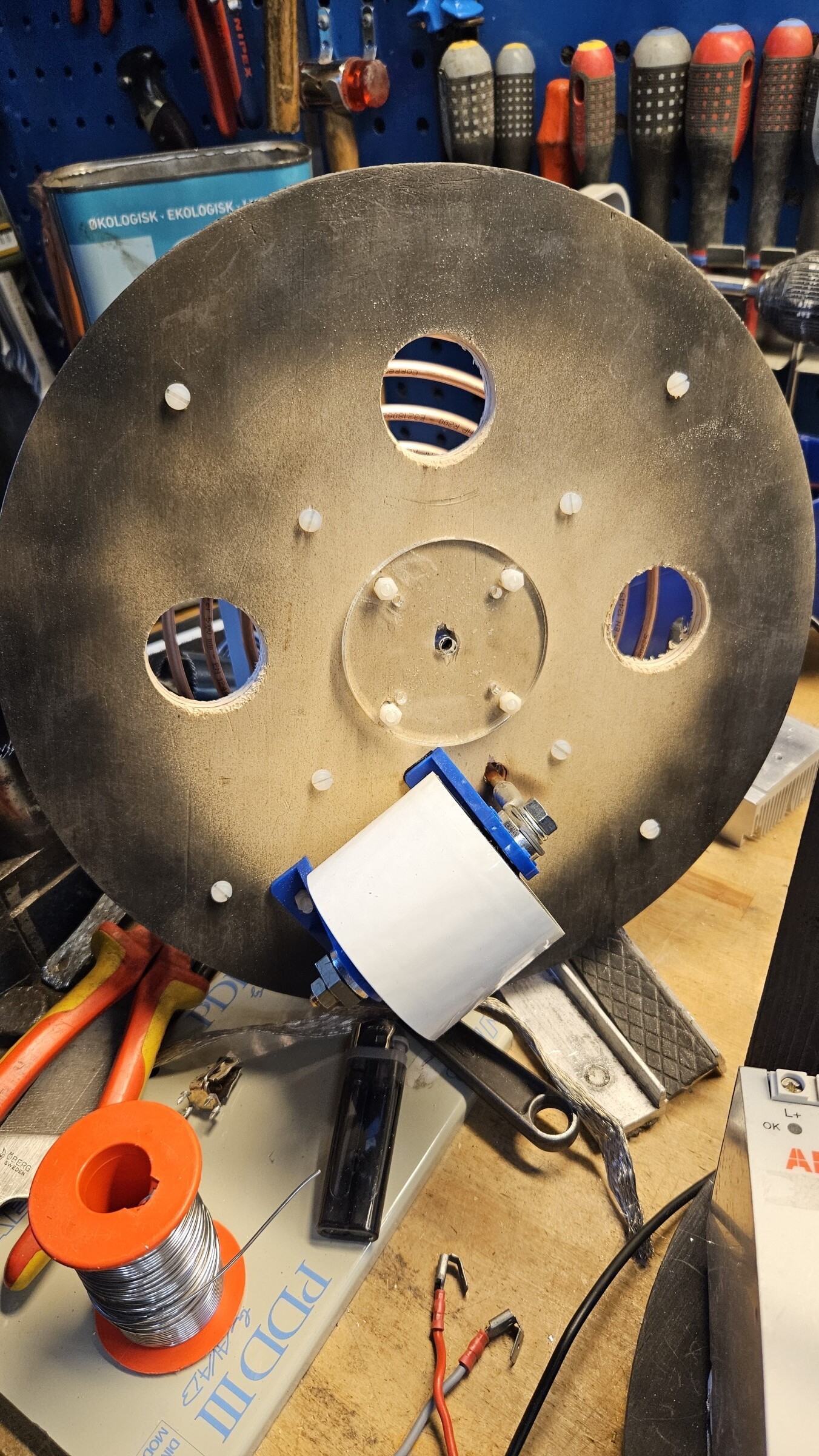
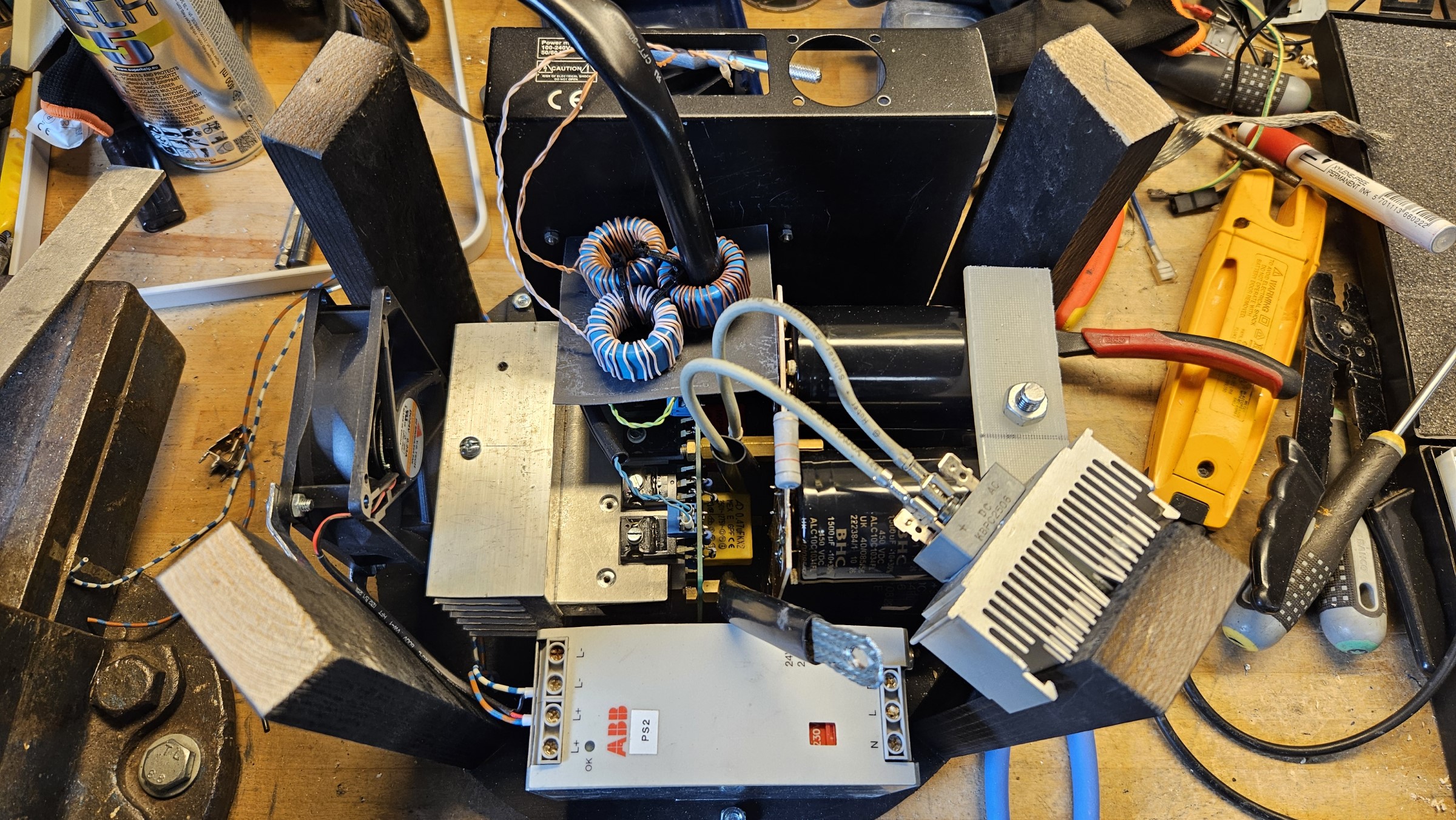
Tesla Coil Base Layout
I initially thought the base, with its 30 cm diameter, was going to make plenty of room for components. It quickly turned out to be very crammed and near impossible to add more needed components. Sensitive components is protected with layers of plastic, mostly for mechanical protection against wires rubbing up against sharp PCB edges and such.
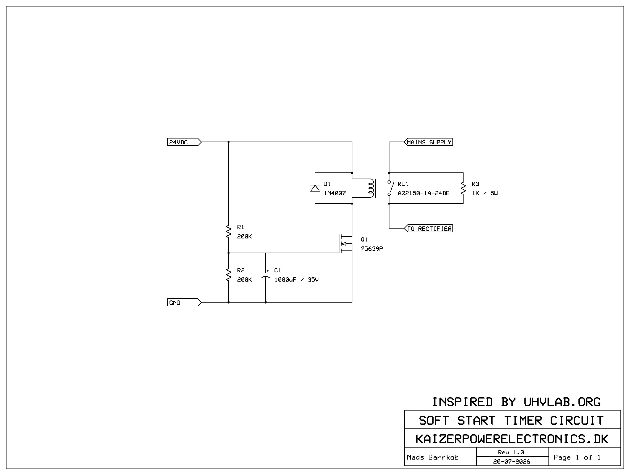
Soft Start Circuit Capacitor Precharging
I used a 5 Ohm NTC for soft start, but it proved to be extremely too small to handle the inrush current of 9000 uF, at least in the scope of the mini circuit breakers tripping from the still high inrush current through 5 Ohm.
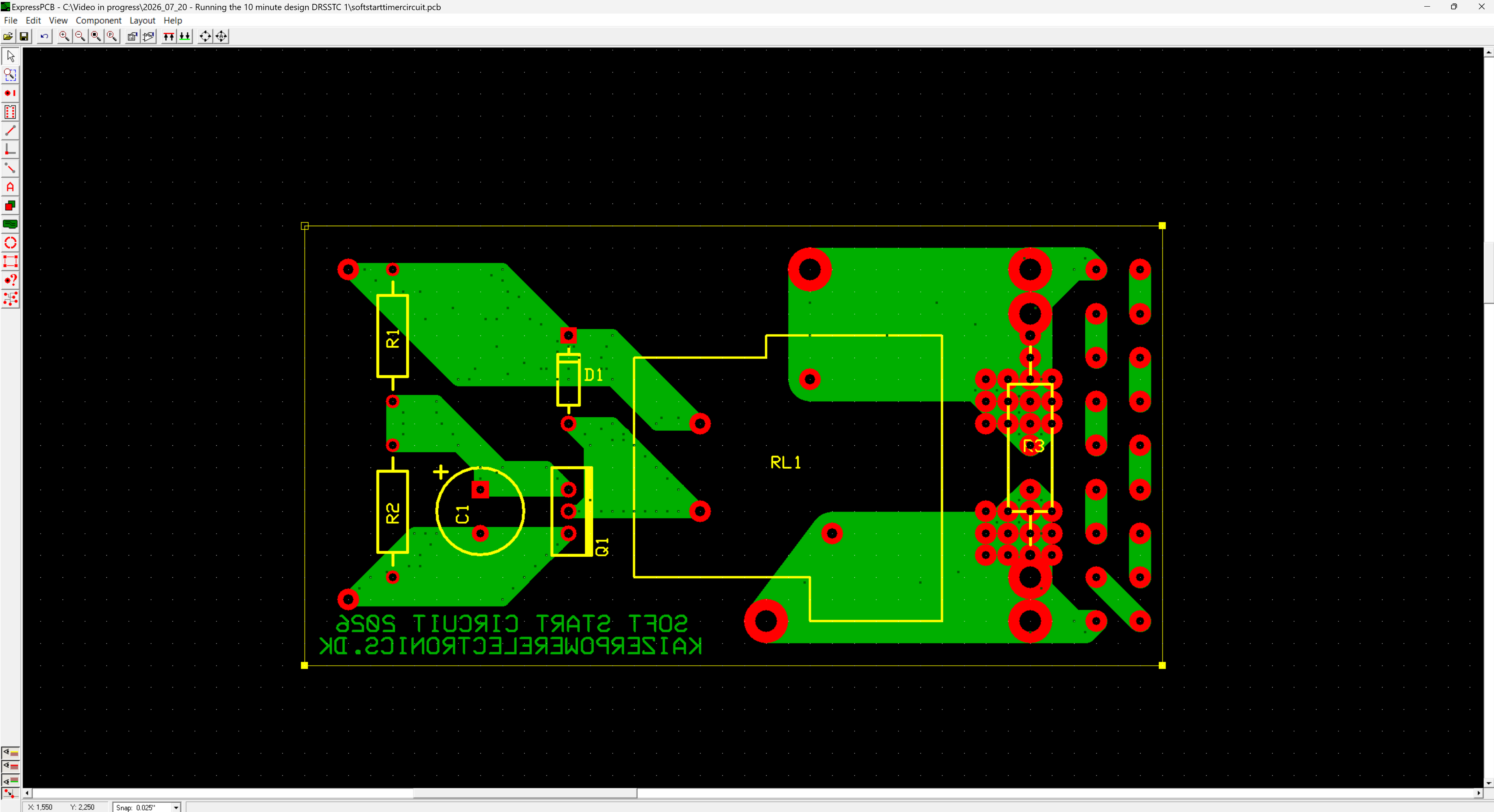
Being forced to use large normal power resistors, a contactor and timer is needed to bypass the resistor after precharge is done. I found a equivalent circuit on UHV Labs and made a version of it to the components I already had. I adjusted the component values to suit my needed precharge time for the 9000 uF electrolytics capacitor bank, so it would not trip my C13 breakers.
Schematics: https://kaizerpowerelectronics.dk/files/projects/2026_02_08_-_kaizer_drsstc_vii/softstarttimercircuit.sch and PCB layout: https://kaizerpowerelectronics.dk/files/projects/2026_02_08_-_kaizer_drsstc_vii/softstarttimercircuit.pcb
Secondary Coil Terminations
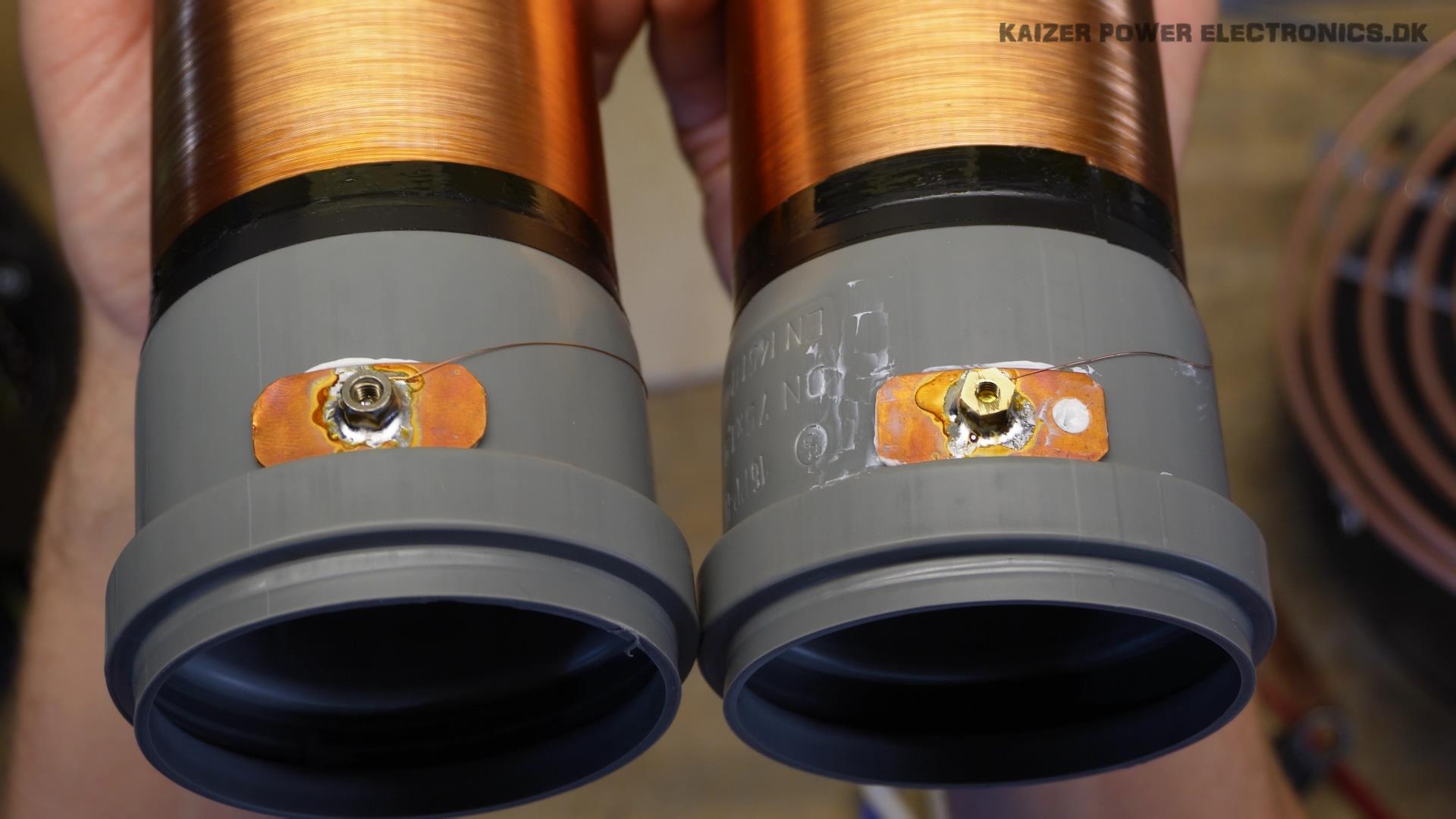
Topload termination is a simple ring cable lug, with plastic removed and secondary coil wire soldered into. Be sure to orientate the wire in a soft curve to not stress it from heat expansion and protect against mechanical stress from topload moving.
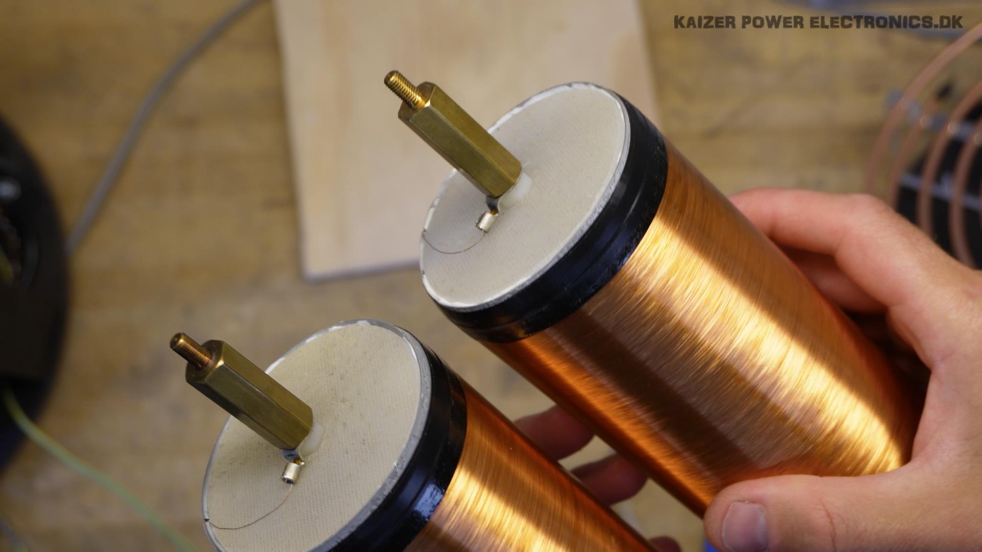
RF ground termination is a piece of copper strip with a brass nut soldered onto it. Be sure to orientate the wire in a soft curve to not stress it from heat expansion and protect against mechanical stress from secondary coil or RF ground connection moving.