This SSTC Design Guide article is to point out some of the design decisions and calculations that is different from a DRSSTC, so this article will not contain a description of all parts used in a SSTC. The following topics are covered by the DRSSTC design guide as the guidance and best practices is the same.
- Rectifiers
- Busbar and primary circuit
- DC bus capacitor
- Secondary coil
- Topload
- Grounding and EMI
- Online design tools
As an example in this guide, I will use the dimensions and properties of my Kaizer SSTC 2 Tesla coil. It is a full-bridge IRFP460 running at 250 kHz, making up to 47 cm sparks, see all construction details on the link.
Primary peak current calculation

To do an easy primary current calculation, to know if the MOSFETs can drive the load, it can be simplified by ignoring primary resistance and DC blocking capacitors reactance as they are very small factors.
First calculate the primary coil inductance for your helical or spiral primary coil. Use one of the two links for the online calculator.
Next step is to calculate the primary coil reactance. f is frequency in Hertz and L is inductance in Henry. Values are written in kHz and uH for ease of reading. The 8 turn helical coil with a diameter of 115 mm, with 1.78 mm wire and 2 mm spacing has a inductance of 10.16 uH.


The peak current for the peak-to-peak square wave voltage envelope can now be calculated using Ohm’s law. I supplied my coil from full-wave rectified 230 VAC, which multiplied with square root (2) for the peak voltage is about 320 VDC.


Conclusion on primary peak current. We now have a basic measure for how much current we are trying to push through our MOSFETs and primary coil. The MOSFETs should as a minimum be able to withstand this, with a safety margin added on top. Voltage rating should have around 33% head room, so if you are feeding the inverter 320VDC, a 600V MOSFET is to prefer.
Primary Geometry and Coupling


There is generally four shapes of primary coils.
- Flat spiral coil (Used in SGTC and DRSSTC)
- Helical coil (Used in VTTC, SSTC and DRSSTC)
- Cone coil (Used in SGTC, DRSSTC)
- Half-circle coil (Used in QCWDRSSTC)
A SSTC will almost always use a helical coil with a high and tight coupling to the secondary coil. Due to the relatively low primary circuit current it is necessary to have a primary geometry that gives a high coupling to get a good energy transfer.
In my SSTC constructions I have often used regular machine tool wire wound directly around the base of the secondary coil, with nothing more than 2-10 mm of insulating material in-between and also to make it able to adjust coupling by moving it up or down. The insulation needs to extend further than the primary coil to avoid flash over damages, as I have experienced.

DC Blocking Capacitor
The DC blocking capacitor is named after its purpose, to block any DC component of a signal to enter the transformer being driven by a half- or full-bridge. A DC offset current may cause an unbalance of the transformer that initiates a runaway process. This can get the transformer saturated and the large current drawn in this mode will damage both transformer and MOSFETs. [1] Calculating the correct value is a vital part of the SSTC Design Guide.
The DC blocking capacitor can either be in series with the primary coil for a full-bridge or in series with the primary coil for a half-bridge that connects to ground. For a half-bridge it can also be two capacitors forming a voltage splitter with a midpoint where the primary coil connects to. This voltage splitter can also be used in a voltage double configuration. The most important factor is that it is a very low ESR capacitor, in order to minimize the switching losses across it. Generally this means that the same type of MKP capacitors used in a MMC is suitable for DC blocking capacitors, given the capacitance is suitable. Below the DC blocking capacitor is the blue RIFA sitting in series with the black wires going out to the primary coil connectors.

DC Blocking Capacitor Calculations
There is two factors to calculate for the DC blocking capacitor. First the capacitor/reactance ratio to the inverter output impedance. Secondly the resonant frequency of the primary coil L and DC blocking capacitor C is much lower than the resonant frequency of the secondary coil circuit.
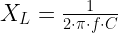
First we can calculate the DC blocking capacitors reactance. f is frequency in Hertz and C is capacitance in Farad. Values are written in kHz and uF for ease of reading. I used two 0.68uF X2 MKP capacitors in parallel.

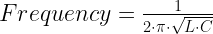
So now we can check the resonant frequency against the Tesla coil secondary circuit frequency. f is frequency in Hertz, L is inductance in H and C is capacitance in Farad. Values are written in kHz, uH and uF for ease of reading.

Being 5 times lower than the resonant frequency, there is no risk at the primary LC circuit resulting in a DRSSTC condition which would destroy the MOSFETs.
The reactance of the two capacitors was 0.468 Ω and the inverter output impedance should be higher than this.


It is worth noting that the inverter output impedance should be almost identical to the primary coil reactance as the pure Ohm resistance of the primary coil is very small.
The DC blocking capacitor reactance is 32 times smaller than the inverter output impedance and the design requirement is fulfilled. A lower capacitance would result in even smaller losses in the DC blocking capacitor.
Conclusion on DC blocking capacitors is that they should behave like a dead short at the resonant frequency of the Tesla Coil or inverter. So anything below 2 Ω reactance should be considered to work.
Gate Drive Current
Many different driving methods are used for SSTC’s and their half- or full-bridge of MOSFETs / IGBTs. Unlike the DRSSTC universal drivers, there is a wide variety of gate drive ICs, transistors or other implemented in different SSTC driver circuits.
It is important that there is enough current and fast enough rise time when driving the gates of the MOSFET/IGBT that switching losses are minimized as much as possible.
Use the MOSFET / IGBT Gate Drive Calculator to estimate the required peak current needed and RMS power consumption for the power supply design.
Published: July 15, 2019. Updated November 11, 2021.
References
[1] Alexander Gertsman, Sam Ben-Yaakov, “Zeroing Transformer’s DC Current in Resonant Converters with No Series Capacitors”, Department of Electrical and Computer Engineering, Ben-Gurion University of the Negev, 2010.
I am trying to recreate your sstc 2 and reviewing this guide I noticed some errors. in the rectance of 1.36uF capacitor you have that it is 2.1352 Ohms but according to my calculations it is 468.103 milliOhms and in the output impedance of the inverter you have that it is 1.6 Ohms and I think it should be 16 Ohms because 320VDC/20 A= 16 , do these errors have any impact when choosing the right capacitor?
Hi Jonatan Baeza
Thank you for the corrections, I should have noticed that XL and Inverter impedance should have been almost the same. I have unfortunately just copy pasted some previous calculations into this guide without checking up on them again, sorry about that.
Kind regards
Mads
What is the necessary voltage rating for the DC blocking capacitor? For example, for a full bridge powered from rectified 230V (so about 320V DC) will 600V be sufficient?
Hi Maks
A headroom of 100% is good. Normally 1/3 over working voltage would be good enough.
Kind regards
Mads
I think your description and calculations are not quite accurate and adequate to circuit you mention.
First note:
You have caluclated current as Amp=320V/XL
And then “Inverter output impedanece” as 320V/Amp, so it simply gives back XL. This is NOT inverter output impedance, which in general constists of MOSFET RdsOn resistance plus filtering capacitors reactance(and some wire resistance if they are long).
Second note:
You have calculated current for coil powered by square wave signal, so reactance (calculated for sine wave) has no sense here, and produces wrong result.
In this case current has triangle shape, and current peak can be calculated as:
Ipeak=Votage/frequency/inductance/4
or
Ipeak=Voltage*period/inductance/4 = 320V*4microSeconds/10microHenrys/4 = 32A
It can be derived from coil current formula:
I=U*t/L,
where ‘t’ is one quarter of full period (because for 1/4 period current is rising from zero in on one direction reaching (+maximum), then for 1/4 period is falling down reaching zero, then for 1/4 period is rising in opposite direction reaching (-maximum), and then after last 1/4 decreasing to zero, and full cycle reapeats) .
Kind regards,
Zbig.
Hi Zbig
I do state quite clearly that “To do an easy primary current calculation, to know if the MOSFETs can drive the load, it can be simplified by ignoring primary resistance and DC blocking capacitors reactance as they are very small factors.”
A inverter driving a resonator like the secondary coil, is not behaving like a regular inverter. The RLC series nature of the secondary coil is reflected back onto the primary coil through the coupling between the coils. Hence the calculations for a sine wave.
Unfortunately it seems that Richie Burnett site is broken, but check out https://www.richieburnett.co.uk/sstate2.html and https://www.richieburnett.co.uk/sstate3.html and maybe try to find them at archive.org for the missing pictures.
Kind regards
Mads
Oi mads para que serve o gdt ?? só uma duvida mesmo.
Hi
have a good time
What will happen if I increase the capacity of the voltage divider capacitors in the half bridge circuit?
I am currently using 470nF capacitors
Hi Arthur
A too high Capacitive Reactance will hinder limit the current flow. https://www.electronics-tutorials.ws/capacitor/capacitive-voltage-divider.html
You could try to match the Capacitive impedance to the load impedance and RdsOn resistance.
Kind regards
Mads