Choosing a switch for a Tesla coil inverter is not a simple task if one looks into all the parameters given in a datasheet, and even more complex if you run the numbers through a IGBT inverter design application note from almost any manufacturer.
This is chapter 3 of the DRSSTC design guide: IGBTs
All datasheet values are given for a specific gate voltage, collector-emitter voltage, current, duty cycle, temperatures etc. They are based on hard switching currents into either a resistive or inductive load, especially those datasheets with resistive loads can seem faster than they would in a inductive application. Tesla coils like the DRSSTC rely on soft switching, for which there is little to no data in datasheets, but generally that means switch times are faster, losses lower and currents switched can be higher.
How to drive a IGBT in the best possible way and maintain what is called “Switch fast as slowly as possible” will be covered in chapter 7: GDT / driver.
How to read a IGBT datasheet [1]
Maximum Gate-to-Emitter Voltage (VGE)
The gate voltage is limited by the thickness and characteristics of the gate oxide layer. Though the gate dielectric rupture is typically around 80 volts, the user is normally limited to 20 or 30V to limit current under fault conditions and to ensure long term reliability.
It is normal practice to drive IGBTs at +24VDC with the Steve Ward universal driver and clones of it that most use. The reason for the gate voltage limit is not so much for protecting the gate itself, it will first break down at some 80 Volt. Higher gate voltage means higher currents can be conducted through the Collector-Emitter. We take advantage of this by pushing the gate a little over its rated voltage to allow us to conduct higher currents through the IGBT, at the cost of higher switching losses. As explained by manufacturers in the following.
It is important to note however that IGBTs exhibit relatively high gain even at high gate-emitter voltage. This is because increasing the flow of electrons by increasing the gate-emitter voltage also increases the flow of holes. The gain of a high voltage power MOSFET however is very insensitive to gate voltage once fully on.
VCE(SAT) – Collector-Emitter On/Saturation Voltage
This is the collector-emitter voltage across the IGBT at a specified collector current, gate-emitter voltage, and junction temperature. Since VCE(sat) is temperature dependent, it is specified both at room temperature and hot.
From these graphs, a circuit designer can estimate conduction loss and the temperature coefficient of VCE(sat). Conduction power loss is VCE(sat) times collector current.
It is important to find a IGBT with as low a VCE(SAT) rating as possible. The conduction losses across the IGBT scales linearly with the VCE(SAT) voltage.
Collector-Emitter saturation voltage lowers dramatically at gate voltages above 12 Volt Gate-Emitter voltage, which is why a IGBT should never be driven with less than 15 Volt. Above 20 Volt the Collector-Emitter saturation voltage does not decline that much, but it is still lessened with higher gate voltage.
VCES – Collector-Emitter Voltage
This is a rating of the maximum voltage between the collector and emitter terminals with the gate shorted to the emitter. This is a maximum rating, and depending on temperature, the maximum permissible collector-emitter voltage could actually be less than the VCES rating. See the description of BVCES in Static Electrical Characteristics.
The most useful IGBTs for DRSSTCs are those with a voltage rating of 600 V and 1200 V as they provide the switching speed and high current ratings that fall within the region of DRSSTCs. Higher break down voltages normally mean slower switching times. Higher voltage would make it much more expensive to construct a MMC / tank capacitor to handle the higher voltage at high currents.
Since we switch much higher currents in a DRSSTC by soft switching, than the rated pulse currents for hard switching, we can not go by the normal 80% of VCES derating for the supply voltage. There will be a risk of voltage spikes punching through the IGBT. For the matter of using them in a DRSSTC, the derating should be 66% of VCES.
BVCES – Collector-Emitter Breakdown Voltage
BVCES has a positive temperature coefficient. At a fixed leakage current, an IGBT can block more voltage when hot than when cold. In fact, when cold, the BVCES specification is less than the VCES rating. At -50 ºC junction temperature, BVCES is about 93% of the nominal 25 ºC specification and at 150 ºC, BVCES is about 110%
This would correspond to a 1200V IGBT can only block 1116 V at its lowest temperature rating and 1320 V at its highest. So as far as voltage rating goes, it is better to have a IGBT running warm compared to trying to cool it with peltier elements or liquid nitrogen.
IGBT Switching Times
The switch times given in a IGBT datasheet is defined within the limits of the four bulletins below. So in reality switch times can be longer, losses bigger and small amounts of cross conduction can occur. The switch times are normally given for hard switching and are thus much slower than what we see in DRSSTC use.
- Turn-on delay time: 10% of gate voltage to 10% of collector current
- Rise time: 10% to 90% of collector current
- Turn-off delay time: 90% of gate voltage to 10% of collector voltage
- Fall time: 90% to 10% of collector current.


Switching times provide a useful guideline to establish the appropriate dead-time between the turn-off and subsequent turn-on of complementary devices in a half bridge configuration and the minimum and maximum pulse widths. They provide a very unreliable indication of switching losses. Because of the current tail, a significant part of the turn-off energy may be dissipated at a current that is below 10% of the load current. The voltage fall time, on the other hand, is not characterized in any way. Thus, two significant contributors to losses are not properly accounted for by the switching times.
It is important to see if the manufacturer follows the unwritten standard or they write the datasheets in their own words. Fuji is known to include Trise times in the Ton time and Tfall times in the Toff times, this makes the IGBT look slower when comparing with others if attention is not given, but all times just added together.
What is the linear region
The linear region is often mentioned when switching losses are discussed or if someone ask “Is this IGBT fast enough for a DRSSTC?” at this particular frequency. I will try to explain the physical mechanism inside the IGBT when it turns on and off, the time period we call the linear region.
The minority carriers in the N- layer, i.e., the base of the PNP part, have to be injected at turn-on and collected at turn-off. This slows down the switching speed of the IGBT.
These minority carriers stored cause the characteristic “tail” in the current waveform of an IGBT at turn-off.

As the MOSFET channel stops conducting, electron current ceases and the IGBT current drops rapidly to the level of the hole recombination current at the beginning of the tail. The tail is important mainly because it increases switching losses, as tail current flows when the voltage across the IGBT is at its highest level.
In resonant / soft switching the turn on losses are primarily given by the parasitic inductance of the IGBT package itself. The turn off loss is very low because the resonant current has significantly decreased by the time we give the off signal to the IGBT. So there are much less holes to recombine in soft switching than hard switching, this is why it can be switched on and off much faster.


Soft switching and zero current switching [2]
As described above the IGBT can be switched on and off faster due to the declining current of the resonant load, we do not have to switch off the current, but we switch when the current is as low as possible.
Only some serious semiconductor physics simulations can tell us how much faster they can switch. The following curves show the difference in switching losses from hard switching to soft switching.

A CM600 that can switch on in a mere 100 ns for both on and off is about 10 times faster than its hard switching specifications from the datasheet. This switch speed reduction can not be assumed to be linear across all sizes of IGBTs and there exists newer die technologies where the junction is optimized for soft switching, whereas most older IGBTs are all optimized for hard switching. Anywhere between 2 to 10 times as fast could be used to extrapolate the switching speeds from the datasheet. This guide will for the following examples assume 4 times faster switch speeds. These oscilloscope shots of a CM600 switching in a large DRSSTC with a phase lead driver were kindly provided by Kizmo. Here the aforementioned very fast switching can be seen in reality.


Zero current switching (ZCS) is only true for a lossless circuit with perfect switches, it is only a term that in the real world should be called “as close to zero current switching as possible”.
To avoid anti-parallel diode losses and cross conduction losses we have to finish switching the current off before passing zero, else the current continues into the negative domain where the other switch/switches would turn on.
With higher frequency the angle of the current is also steeper and thus we have to switch off larger currents as frequency goes up, this is also a reason why larger Tesla coils that switches thousands of Ampere have to run at lower resonant frequencies.
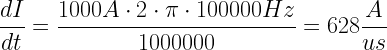
If we have a CM300 DRSSTC running at a resonant frequency of 100 kHz and switching 1000 A the rate of change of current would be:
A CM300DY-24H IGBT have a total of 700 ns (Toff and Tfall) time, dividing by 4 gives us 175 ns, so switching off will begin as the collector current is still at 110 A.
So soft switching or zero current switching 1000 A will have less then 20% of the turn off losses seen in the datasheet for hard switching 110 A.
The same calculations and conclusion is valid for turn on losses.
Thermal impedance
Thermal impedance is a important parameter if you want to understand why we can switch currents much larger than those the IGBT bricks are designed for.
In the graphic below the red box shows the typical pulse duration in a DRSSTC, 200 us. The three lines mark from top and down what corresponds to 100 BPS, 50 BPS and last single pulse.
This is a example of a graph, it is not specific to a CM300 or CM600, it is only showing how to read out a value from a duty cycle.

D is the relative duty cycle and is calculated from full square wave period. D = t1 / t2 where t1 is the on part of the period and t2 is the off part.
So for 100 BPS:
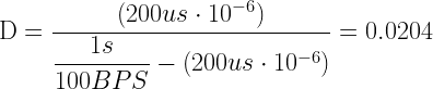
Comparing the read out according to D = 0.02, 0.0081 K/W to the 0.17 K/W rise from a 50% duty cycle given in the datasheet example, the temperature rise at 200 us at 100 BPS DRSSTC operation is a factor 21 lower. Taking it to the extreme, at 300 BPS with D=0.064, 0.012 K/W it is a factor 11.33 lower than the 50% duty cycle. Further reduction could be made as the resonant current is swinging maybe 10 times through the 200 us on time and it is thus less than half of square wave area in terms of losses.
So a very rough estimate is that the switching losses should in best worst case scenario still be 20-40 times lower than those given for hard switching, assuming that we can cool that losses off between pulses, which we will look at next.
Fmax1 and Fmax2 switching speeds
Fmax1 is the maximum frequency rating at a very specific set of test parameters and its curves are not always to be found in datasheets, Switching speed in kHz vs. collector current. The measure of Fmax1 is only valid for low currents as it solely looks at the switching times and does not take switching losses into consideration as there are virtually no heat generated from switching very low currents. In regard to DRSSTCs, Fmax1 is of no interest to us.
Fmax2 is the maximum switching frequency calculated from the switching losses and maximum junction temperature. Fmax2 will in 99% of cases, for hard switching, result in a lower frequency than Fmax1. It can even be the other way around for DRSSTCs as we operate with very short on times.
As an example I will calculate the maximum frequencies for a Mitsubishi CM600DU-24F IGBT brick for a DRSSTC with 2000 A primary current. 200 us on time, 200 BPS, 600 VDC supply, 24 VDC gate drive, 5 Ohm gate resistors.
We want Tjunction to stay below 80ºC and have Tcase cooled to stay below 50ºC. A advisable rule is to keep the temperature ripple below 30ºC, we often use second hand IGBT bricks and we do not know their usage history. To avoid real fast degeneration of die and bonding wires inside the IGBT, we will aim to reduce large temperature swings.
It is given by Microsemi [3] that for hard switching all the switching times should not last longer than 5% of the on time. Since soft switching have under 20% of the losses as we discovered earlier, we will be bold and calculate with 10% duty cycle. We will also assume the on/off switching times to be 4 times faster due to resonant switching, as described earlier.

Plotting in the numbers gives us the following.

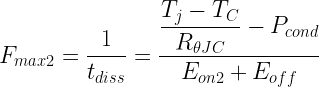
The thermal limit to frequency is derived from the power dissipation formula which is based on conduction losses, switching losses and the time required to dissipate those losses.

The higher the conduction loss, the more time is required to dissipate the switching losses. So the inverse of tdiss is the maximum frequency. RθJC is the junction to case thermal resistance, Tj is the temperature of the junction and TC is the temperature of the case.
By extrapolation of the output characteristics performance curves, we get VCE(sat) is approximately 4V at 2000A and Tjunction 80ºC.

Our duty cycle is derived from 200 us on time and 200 BPS with corresponds to 4%. It is already a very low loss despite that we calculate it for a square wave and not the actual number of primary cycles we have in a DRSSTC burst, to account for the ringing sinusoidal current waveform we could assume the duty cycle to be at least half of the above, so we continue with 0.02 duty cycle.

RθJC is in the case of the CM600 given as 0.081 K/W, but we also have to look at the transient thermal impedance characteristics, as these presented as a normalized transient thermal impedance Zth(JC). The steady state thermal impedance given as RθJC have to be multiplied by the factor gotten from the normalized graph according to the duty-cycle. At 0.02 we are as close to factor 1, so I will proceed with 0.081 K/W. It is worth noting that this is a worst case value where case temperature is not measured directly under the chip, if we used that value we could use the lower 0.032 K/W.

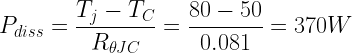
Total power that can be dissipated within our temperature limit is
To find the switching losses, we have to estimate the change of current rate from the frequency that we would like to design the DRSSTC for.

For a CM600DU-24H it is given that Toff and Tfall is 1100 ns in total, 275 ns when assumed 4 times faster, so switching off will begin as the collector current is still at 138 A. Ton and Trise are 650 ns in total, 167 ns when assumed 4 times faster, so switching on will begin as the collector current is still at 83 A. We can now find the switching losses from the energy loss curves, find the energy values for 138 A off and 83 A on and divide the read out value by 10 to derate for the exponential decay of the current wave form.

So we can read out that Eon is 5 mJ, Eoff is 25 mJ and we take 20% of the on / off loss to account for soft switching and the difference in rise and fall curves as seen earlier. As the datasheet example above is given at 15 V gate drive, we can only assume the losses to be less as we drive the gates harder at 24 V.

We can now calculate our thermally limited switching speed for 2000 A and temperature limits.

Just because the junction can withstand this switching speed when the switching losses are used in the calculation, it does not mean that we can actually drive the IGBT at this speed with a regular DRSSTC universal driver. It is however a important check to see if we can run seemingly slow bricks at higher speeds than what could be expected in a hard switching application.
IGBT Terminal current limitation
In datasheets for newer IGBTs, like the Mitsubishi 6th generation bricks like CM400, CM800 and CM1000 there is a star note to the collector current.
“DC current rating is limited by power terminals”
A DRSSTC does not operate at DC, but we operate them at far higher pulse currents, so we do have a similar problem with heating of the connections. The terminals could be made from thinner copper than earlier models and thus there is now a warning against current limitations in the power terminals. If new IGBTs are used, it could be a good idea to construct the busbar in such a way that it can dissipate as much heat from the IGBT terminals as possible.
IGBT conclusion
If we want to switch currents larger than the pulse current specifications, we can take advantage of driving the gate harder by applying a voltage 20% higher than the rating. It is normal to drive a 20V rated gate by 24V.
Collector-Emitter voltage VCES should be kept at a maximum of 400V for 600V devices and 800V for 1200V devices.
Collector-Emitter On/Saturation voltage VCE(sat) should be as low as possible. Somewhere between 2 to 3 V given in the datasheet example should still be good when extrapolated for our high peak current.
The temperature ripple between junction and case should be kept at a maximum of 30ºC.
We have seen that datasheet where only information for inductive hard switching is given, it can still be used to extrapolate data to an approximation of soft switching used in DRSSTCs.
Calculation of the Fmax2 frequency is the only way to check your IGBT against your design goals for a DRSSTC, if not just basing it on someone else’s proven design as found below in the table.
Reality have shown that it is possible to drive a CM600 brick at much higher currents and frequencies as we calculated for the Fmax2 frequency. It should however be noted that expected life time of the IGBT might be in the hundreds of hours instead of 10s of thousands, when driven so hard.
The real limitations of frequency the IGBT can be driven at will be its internal parasitic inductance and the power required to drive the gates, which will rise dramatically at high frequencies for large gate capacitance. The widely used universal driver from Steve Ward or similar is used for the coils mentioned in the following table. Driving a large brick much faster will require a much more powerful driver.
Table of PROVEN switching speeds for different IGBT switches
| Frequency | Peak current | Part number | Proven by |
| 34 kHz | 2500 A | Powerex CM600HA-24H | fh89 on HVF |
| 35 kHz | 6000 A | Infineon FZ1200R12KL4C | zilipoper on 4hv.org |
| 35 kHz | 4000 A | Powerex CM600DU-24NF | zrg on 4hv.org |
| 35 kHz | 2000 A | CM1400DU-24NF | Adam Munich on 4hv.org |
| 37 kHz | 1500 A | Powerex CM600DU-24NF | Mads Barnkob |
| 36 kHz | 1300 A | Powerex CM300DY-24NF | Fabrício Franzoli |
| 40 kHz | 1000 A | 2x CM300 Full-bridge | Benjamin Lockhart |
| 42 kHz | 2500 A | Infineon FF900R12IP4 | Алекс Ккк on Facebook |
| 42 kHz | 1300 A | SKM400GB124 | Finn Hammer |
| 42 kHz | 1200 A | Powerex CM300DY-24 | Dzejwor on 4hv.org |
| 60 kHz | 1000 A | CM300DU-24NFH | Benjamin Lockhart |
| 70 kHz | 500 A | IXYS IXGN60N60C2D1 SKM200GB123 | Mads Barnkob |
| 70 kHz | 750 A | CM300DY-24H | Hydron on 4hv.org |
| 72 kHz | 700 A | CM300DU-24NFH | Gao Guangyan |
| 73 kHz | 1130 A | Infineon FF450R12KE4P | Felix B on HVF |
| 74 kHz | 800 A | SKM300GB128D | Mathieu thm on HVF |
| 75 kHz | 490 A | Semikron BSM75GB120DN2 | mmt on 4hv.org |
| 75 kHz | 800 A | Fairchild HGT1N40N60A4D | Steve Ward |
| 80 kHz | 750 A | Semikron SKM200GB125D | Hydron on 4hv.org |
| 87 kHz | 850 A | CM200DU-24F RTC removed | Alex Yuan |
| 120 kHz | 450 A | Powerex CM200DU-24F | Gao Guangyan |
| 125 kHz | 415 A | Semikron SKM150GB128D | Mathieu thm on HVF |
| 128 kHz | 300 A | FGH60N60SMD | GrantV on HVF |
| 140 kHz | 550 A | Semikron SKM100GB125DN | oneKone on HVF |
| 150 kHz | 350 A | CM75BU-12H | Fabrício Franzoli |
| 150 kHz | 500 A | IXGN60N60C2D1 | Alex Yuan |
| 150 kHz | 350 A | HGTG40N60A4D | Fabrício Franzoli |
| 200 kHz | 700 A | Semikron SKM50GB100D | brtaman on 4hv.org |
| 230 kHz | 300 A | Semikron BSM150GB60DLC | Flyingperson23 on HVF |
| 235 kHz | 300 A | Semikron SKM75GB12T4 | David Issler |
| 270 kHz | 300 A | FGA60N65SMD | Alex Yuan |
| 327 kHz | 300 A | IXYS IXGN60N60C2D1 | Mads Barnkob |
Table of FAILURE switching speeds for different IGBT switches
| Frequency | Peak current | Part number | Proven by |
| 56 kHz | 3500A | CM600HA-24H | Kizmo at 4hv.org |
| 42 kHz | 2000A / 500 BPS | SKM400GB124 | Finn Hammer |
| 70 kHz | 500 A | IXYS IXGN60N60C2D1 | Mads Barnkob |
| Previous topic: Busbar and primary circuit | Next topic: DC bus capacitor |
Published: February 5, 2015. Updated: March 3, 2021.
References
[1] International Rectifier “IGBT Characteristics”, Application Note AN-983, July 2012.
[2] Dipl.-lng. Markus Krogemann. “The Parallel Resonant DC Link Inverter-A Soft Switching Inverter Topology with PWM Capability”, Submitted to the University of Nottingham for the degree of Doctor of Philosophy, February 1997.
[3] Jonathan Dodge, P.E and John Hess. “IGBT Tutorial”, Application Note APT0201 Rev. B, July 1, 2002.
Hi,
Great work!!!
What do you think about IXGN 200N60A is good option?
or IXGN200N60B3.
Hi Arc
I used the IXGN60N60 in my DRSSTC 1: https://kaizerpowerelectronics.dk/tesla-coils/kaizer-drsstc-i/
The IXGN200N60 is a new IGBT that is faster, has lower losses but the same pulse rating as the 60N60. It is a good IGBT, but you should not push it above 500A peak.
Kind regards
Mads
Hi Mads,
Thank you for reply. Yeah I seen your DRSSTC 1. Is nice and well done. About 200N60 yep I also pretty sure that will be working well, I try it in current my project.
Best Regards,
Arc
what is the full form of bps
Hi NIKUL panchal
BPS is bangs or burst per second.
I listed the most common shorting here: https://kaizerpowerelectronics.dk/tesla-coils/drsstc-design-guide/drsstc-faq-frequently-asked-questions/
Kind regards
Mads
I need to make an induction furnace rated at 50kw. And I would appreciate any help.
Hi, i wondered if it’s possible to use an igbt like IXGN200N60B3 for a 60kHz TC despite it didn’t have any anti-paralel diode. Thank you in advance for any kind of reply 🙂 Just exploded 2 of my IXGN72N60C3H1 at 600-700A and looking for more juice….
Hi Samuele Gobbi
Miniblock IGBTs silicium die size is really not much bigger than a TO-247, so pushing them above 600A is asking for explosions. Even the IXGN200 which has a higher “rating” can not dissipate more heat than its smaller predecessors.
For such a low frequency coil at 60 kHz, you should really upgrade to proper bricks like CM300, SKM400 etc. which can take 1500A easily.
Kind regards
Mads
Hello
I have got a question: In the thermal impedance chapter you read from the chart that the thermal impedance will be 0,0081 K/W for the given duty cycle and ontime. But when you calculated the maximum allowed dissipation for the 30°C temperature limit, you used 0,081K/W instead of 0,0081K/W.
Did I miss something or is that a mistake?
I also bought Infineon/Eupec FZ800R12KF4 Bricks for my new large 315mm DRSSTC project. What do you think about these bricks? They should handle 3000A peak without a problem according to my calculations.
Thanks for reading
Greetings
Phoenix
Hi Phoenix
I checked my spreadsheets on my PC and it seems I went with much more conservative R0(JC) values there. It is a lot of guess work on best assumed principles, but I agree that my article does not describe it in enough details, so you assume that the 100BPS/200us I show first should be the number I use further down, but here I actually calculate it for 200BPS/200us. Even that corrected to graph readout would be around 400 kHz, so I am just nursing those CM600s 🙂
Kind regards
Mads
hi Mads
I have 4 IXGN200N60 igbts laying arround and i want to use those for my drsstc, the problem is that this igbts don’t have an antiparallel diode.
How can i add an antiparallel diode to those igbts and what diode should i use?
i will appreciate your help
Greetings
Mateo
Hi mateo
You can add a external ultra fast diode, that has the adequate current/voltage rating and has a reverse recovery speed that is fast enough for your resonant frequency. You just add it across the terminals of the IGBT as it would sit between C-E as the parasitic diode normally does.
Kind regards
Mads
Do you think this will work well for a tesla coil like your drsstc 1? MUR860
Hi mateo
Trr is twice as long on the MUR860 than the parasitic diode of the IXGN60N60C2D1, so you have to check if 70ns is too slow, which I think it is not, but do the math to your setup and see if its below 10% of your duty-cycle.
Kind regards
Mads
Hi, i don’t really understand how could i know what is the maximum frequency that an igbt could work properly.
I have a coil that resonates at 160khz and i want to use an h bridge with two cm200dy-12h, could i use it for a peak of 600a?
Hi Mateo
You have to do the Fmax2 calculations as you can see an example of in this article, it all comes down to what temperature rise you find acceptable for your application.
Kind regards
Mads
Mads, why don’t you set up an online tesla clinic and charge so much per minute, you would clean up. I would use your service and sure many many other would also. Good info is hard to come by. Probably would not have to work again.
Hi Shaun E Noggle
Thank you for the kind words 🙂 I have thought about hosting live youtube sessions where people could ask questions like that.
You are always welcome to use my contact form to ask a question or better, sign up at https://highvoltageforum.net and you will not only get help by me, but also a lot of other very knowledgeable coil builders.
Kind regards
Mads
Hi Mads,
Keep up this amazing work, you’re an important reference that always makes these cool things more understandable!
Just got 4x FZ1200R12K’s IGBTs from Finn.
2x FZ1200R12KF1 and 2x FZ1200R12KL4C (slightly different from different generations).
I’m trying to figure out the best way to wire them, the main concern I have is shoot-through which seems to be more likely to happen to different parts on the same side of the bridge and this was exactly what I intended to do, KL4C top and KF1 bottom transistors.
I would like to know if you’ve ever written something about how to calculate gate resistors (rise/fall times) to avoid this kind of problem on slightly different transistors, I’m planning to use Ron=5R1 and Roff=0R51 and i’m not sure if it’s enough.
Cheers
Hi Fabricio
Thank you very much for the kind words 🙂
Calculating gate resistors is not really useful unless you have a full and “perfect” simulation model of your circuits parasitic inductances and so on. The art of adjusting the gate resistor doing testing to minimize ringing is a practical work and there is not much to be done beforehand, than choose a known good value in the range of 2-15 Ohm.
If you predict this to be a problem, you could make it easier to exchange or change between different gate resistors, maybe with jumpers, rotary switch or something and have maybe 4-5 jumps of 0R5 between IGBT models.
I reminds me a bit of building my dual VTTC where I had to adjust feedback individually to the tubes instead of adjusting the feedback network, it was much easier to gain even control from that. So perhaps you could also look into having a tapped GDT where you give one of the IGBT one turn less than the other.
This is all just thoughts, nothing I have tried on such a large IGBT brick.
You should post your progress on https://highvoltageforum.net 🙂
Kind regards
Mads
Hi Mads,
First of all…
Keep up this great work, this is a super informative website!
You and your builds are part of the reason why I want to build a DRSSTC!
I have built a few HF SSTC’s runnin on mains voltage 230V they all consumed around 2-6A in CW.
I came across this website and now I want to build my first DRSSTC using IGBT’s.
I found the IXGN200N60B3 which seem to be an upgraded version of the standard IXGN200N60A.
They have a prettey low Vces compared to other IGBT’s, really good Rthjc, powerdissapation and higher peak current capabilities than the A version.
I am still a student and have never used IGBT’s before so I’m kind of in the dark!
Could you do me a favour an look over this IGBT and tell me if I can push it to around 700A-900A at around 133KHz? And if not, then how far could I push them while still playing safe? The frequency is not a fixed parameter, it can be changed if necessary.
Best Regards from Germany
Hi Nikan
Thank you for the kinds words, I am happy that I can inspire new people to get into the higher tiers of the high voltage hobby 🙂
My personal experience with the SOT-227B/miniBLOC package IGBTs is that they are re-packaged TO-247 silicon dies, so they are very far from being as sturdy as a regular IGBT brick. I would not push it beyond 500-600Apeak, unless you have the money to push them to the limit, have them explode and then turn it 20% down 🙂
The frequency is pretty low for these fast switches, I run my small DRSSTC at 300kHz with the IXGN60N60 miniblocks.
Kind regards
Mads
Hi Mads,
Thank you for your help, I really appreciate it!
Alright I will set the limiter to 600A peak.
300KHz seems obscure high for me, I thought IGBT’s are way slower than that.
What is the reason for repackaging these dies, if they are similar to 247 dies. Only for better power dissapation???
By the way I ust saw that the IXGN200N60B3 does not have a body diode.
If IGBT’s are made by combining a transistor and a mosfet how come it does not have one.
I was thought that these body diodes are a side product of monufacturing processes on mosfets.
Do you have a video of your coil running at 300KHz?
Again Thank you very much.
Best Regards, Nikan
Hi Nikan
Small and modern IGBTs can go up into the 500 MHz region.
The parasitic body diode of the IGBT has been removed by some manufacturers, for wider design freedom, as the built-in diode is rather slow and lossy, most designers will always add a external fast diode anyway, if reverse conduction is needed.
My DRSSTC2 runs at 300’ish kHz: https://kaizerpowerelectronics.dk/tesla-coils/kaizer-drsstc-ii/
All my Tesla coil videos are to be found here: https://www.youtube.com/playlist?list=PLw4xMO1xCMSWzmVlGLVac0pnz2Yi11HB7
Kind regards
Mads
Can FGA60N65SMD work with 370kHz resonant frequency?
Take a look at these threads:
https://highvoltageforum.net/index.php?topic=193.0
https://highvoltageforum.net/index.php?topic=236.0
https://highvoltageforum.net/index.php?topic=413.0
https://highvoltageforum.net/index.php?topic=522.0
Up above their is a formula: also sent a snippet
.1
450ns+300ns+200ns+800ns
(————————————-) *10 -9
4
the answer is 230khz, how did you get that answer. I just don’t get the same thing. Thanks
Hi John
I put this into Excel and got 228 kHz
=0,1/(((450+200+800+300)/4)*10^-9)
Kind regards
Mads
This was with highest rated current. Here is the part number IGBT : IRG4PH50UDPb. The specs are:
VCES: 1200 V
Icm/Ilm: 180A
Vge: +/- 20V
I someone with enough experience can check out the datasheet and tell me how large coil can they handle. I plan to use 4 of them. Thanks a lot
Hi Marko Pesic
For TO-247 devices, even with a two in parallel, so you have 8 switches for a full-bridge. I would not build anything larger than my Kaizer DRSSTC 2: https://kaizerpowerelectronics.dk/tesla-coils/kaizer-drsstc-ii/
For larger coils, its just easier and more robust to use IGBT bricks. There is no point in using many small and fast IGBTs, as larger coils drop fast in resonant frequency. The high speed and low current of a TO-247 is no longer a good option. You need high current and as-fast-as-possible IGBT bricks there 🙂
Kind regards
Mads
Thats what i thought, the only other igbt i could find in my country are some bricks that are 1700v and 100A but i dont think that 100a is enough. I would want like a 3 or 4 foot or like around 1 meter lightings but i dont think thats posible. I have built 2 sgtc which do give me around 3 foot each something like that but i dont like then at all plus they cant play songs
Hi there, i was wondering if this was a good IGBT brick. SKKD700/16 this is the psrt number. I think of building the DRRSTC 3 can i use these bricks for it, also i dont know am i getting ripped off or not but they are about 550€.
Hi Paul
SKKD700/16 is a double diode brick, not a IGBT. Something like CM600 IGBT bricks should be around 50-100€ when used.
Kind regards
Mads
Hello Mads, can you tell me if igbts BSM200GB60DLC can handle 800Apk?
Infineon-BSM200GB60DLC-DS-v01_00-en_de (1) (1)
Hi Matheus. You will have to calculate it yourself from the information on this page 🙂
Kind regards
Mads