Teardown of a 8 kW induction cooktop, supplied from 2 single phase mains and neutral. Modular construction with two inverter modules and changeable coils. To get a full explanation on Quasi-Resonant induction heaters, check out my teardown and hacking videos on the IKEA Tillredda induction stoves.
Induction Heater Coils
The induction stove coils are almost all identical and the differences in the size of each cooking zone is purely done in software or configuration on the PCB. Coils are made from litz wire in insulating foam and heat reflecting materials. This is to avoid heat from the pan heating up the coils, which struggle enough with heat from skin effect losses and proximity effect.

Induction heater inverter
The 8 kW induction stove inverters are two separate modules which each has two cooking zones. Each module has a common input, noise filter and bridge rectifier. Each cooking zone and induction coils is connected to separate half-bridge inverters which uses 4 uF of DC bus capacitance and two 0.68 uF / 800 VDC 50 kHz resonant capacitors.

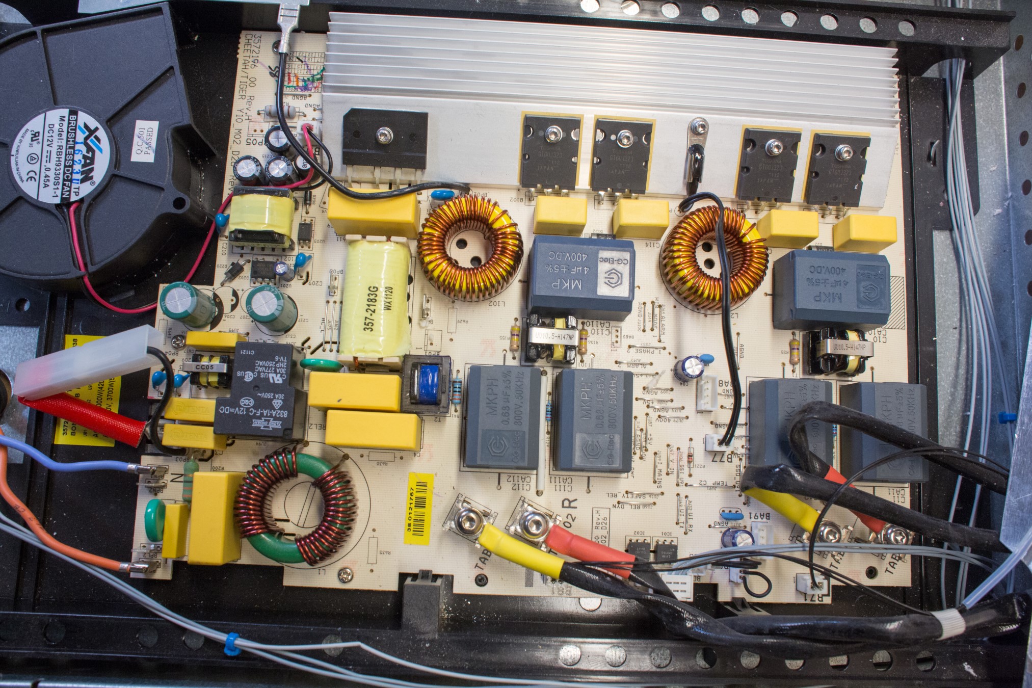


8 kW Induction Cooktop Parts
First the input bridge rectifier is a Chinese brand model D25XB60, which is a 25 A at 600 V rectifier diode. Secondly the IGBT is a Toshiba GT60J323 in a TO-3P package. The IGBT is rated for 33 A continues current at 600 V or 120 A pulsed current. To learn more about power electronics and discuss high voltage and high current experiments, visit the High Voltage Forum.


Thirdly the controller that is used on all printed circuit boards is a ST Microelectronics ST72325 8 bit microcontroller. This had built in Flash/ROM, ADC, timer, SPI, SCI and I2C interface. All the controllers are therefor most likely communicating over I2C and not CANBus as mentioned in the video.


I just found this site. Really good stuff man. I hope you’re still at it. Not much left in the way of individual experimentation and knowledge especially in this field. Hope you’re well. Keep it up, brother.
Cheers
Hi Jay
Thank you very much for the kinds words, it is encouraging to know there are readers 🙂
I am still at it and continues to write about my projects and make Youtube videos 🙂
Kind regards
Mads
I found this site by looking for info on these induction cookers. I’m not that good at electrical stuff, but got an idea if I could use this cooker with broken top as a heater for rusty bolts. I did some experiments and it just has too much electronics and safety and throws me various errors, mostly that there is no cookware. Any idea if I can bypass smart electronics and use same coils or connect special coils and make it work to heat bolts? Or just tear it down to basic components and solder some basic inductor?
Thanks! 🙂
Hi Giedrius
You are better off looking for a ZVS induction heater for bolts, a cooker needs pan detection to avoid over-current situations where it will burn itself to the ground 🙂
Kind regards
Mads
Hi Mads,
Through a mate in Tasmania I found your IKEA teardown of the induction cookers. Very good testing and thorough work, great! With some friends we try to use this cooker for an attempt to replicate the ‘ENKI’ bi-filar coils with heatlamps. Looks promissing, but we have trouble measuring the output of the heatlamps. I send you a comment on that the other day, but maybe it got lost or your are burried in loads of comments like this haha. Do you still have your setup somewhere? I can try to get you some of these coils so you can do some tests yourself. Can I interest you on this? Maybe for some beer(s) :-).
Kind regards
Hans Scholte
Hi Hans
I got your email and was keeping it in the back of my head, thinking about the reply. I prefer answering here, so everyone will benefit from the conversation 🙂
These cheap induction stoves are built to work on the brink of self-destruction. My experience is that any change in the LC circuit, be it inductance or capacitance, will throw the circuit off balance. The off balance is only in regard to the current handling of the single transistor, so slight changes in frequency or current, will tip the heat dissipation of it.
Either use the original coils and change your work load to fit the conditions of the stove, or then you would be better off building a simple half-bridge or full-bridge inverter from scratch. The control systems of the stoves are not that easily hacked, and are certainly not open source.
Kind regards
Mads
Hi Mads!
Big TY for getting back to me. After I dropped some questions to you I noticed you did much more on the induction cooker than your 2 videos of some years ago. Most others that did testing/ replicating what JL Naudin did in 2010 (?) only tried 1 bifilar coil on the glassplate and had trouble getting it to work. From Canada there is a guy calling himself ‘ENKI’ and some other named, but his name is Willi Filsinger. Willi found out that combining multiple bifilar coils on the cooker gives great results, claiming to light up 4 – 6 halogen lamps of 500 W. Thing is it is difficult to measure whether it is really 2000 or 3000W. ‘Cheap’ measurement tools give the impression you have great results, but as you already know ‘there is no free lunch’; claiming is 1 thing but achieving solid results is another. Now Willi sells his special coils for $2000 a piece. He also sold one to a ‘friend of a friend’. Anyhow the YT link I send you of Doug is this coil and Doug is now fighting to replicate the results of this coil-setup. It’s 2 times a bi-filar coil with capacitors in between and configured in a specific way. I suppose you are too busy with projects that generate some income, but if you are curious (or one of your readers of your website) I can try to make a replication and send it to you to discuss some sort of testing procedure, based on your knowledge and experience with these hv induction cooker. Btw, I got me 2 Ikea cookers, so I can do some testing myself but not as advanced as you have in your lab.
Thanks again for your help already!
Regards, Hans (Groningen)