Testing the 10 Minute DRSSTC Part 1: UD2.9 Driver and DC Bus Capacitors
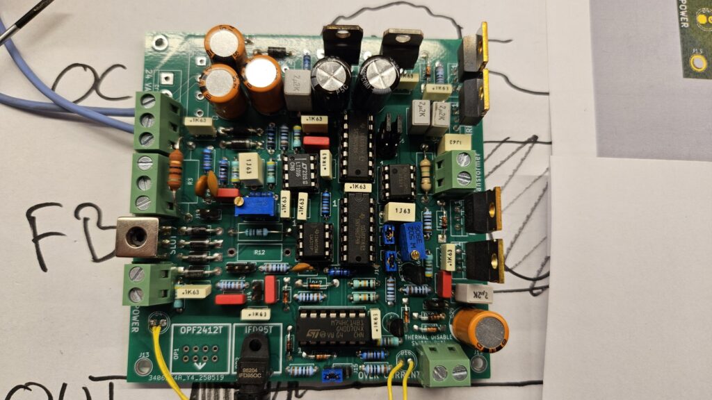
This article and video focusses on configuring and validating the Universal Driver (UD2.9) functions and reforming the DC bus capacitors. Starting up a new electronics circuit can be done with various degrees of precaution. The easy way would be to apply full voltage and all inputs / outputs connected and see that the circuit behaves […]
Testing the 10 Minute DRSSTC Part 1: UD2.9 Driver and DC Bus Capacitors Read More »