
I picked up two of there 5.5kW frequency inverters from a scrap yard. Both assumed to be thrown out due to malfunction. I took them home to dismantle them for parts to use in other projects.
First we have the front and two stickers, one with specifications and the other with end of life information. These are fairly new units from 2013.


Removing the front metal plate and display unit, in the upper left corner we can see the house keeping power supply part of the main board, just below we can see the input filter PCB and upper right corner in the beige plastic we have connector and terminals for input/output control signals. A close-up of the input filter show that we have a varistor between phases and two 1 uF capacitors in parallel for each phase to ground.


The main board has the low voltage power supply for logic and gate drive in upper left corner. All control is done in the upper right corner, at first is the 3 phase PFC with output wires to the 3 SCRs for the input rectification, to the far right is brake chopper part. Below that there is resistor chains used for some kind of voltage feedback from the brake chopper and at the bottom of the board is the three gate drivers with each their connector with coloured cables red, yellow and blue that goes to the gates of the main IGBT brick.

With the main control board removed we can see the three phases from input terminals that go to connect at the SCRs and their gate drive wires sticking out at the top. Below is the brake chopper with wires going back for voltage feedback. The beige box with the red wires looping through three times is the current transformer used for monitoring of the inverter output current to the motor terminals.

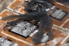
All capacitors needed for filtering and snubbering around the SCRs and brake chopper is mounted on the PCB that is turned upside down here. The SCRs are Semikron SKKH 57 / 22E H4, rated for 2200 Volt at 57 Ampere.


With all boards and wires out of place we can see the main power board. In the upper left corner is four connections to a choke that is placed underneath with the heat sink. Just below we can see the + and – marking on the PCB where the two electrolytic filter capacitors are mounted, also underneath with the heat sink. The choke and capacitors are down there to be cooled by the same air flow used for cooling of the heat sink.

The main IGBT module is a Semikron FZ100R17KE3 rated for 1700 Volt at a mere 200 Ampere repetitive pulsed current. The brake chopper is a Semikron SKM145GAL176D single IGBT rated for 1700 Volt at 100 Ampere.


The two electrolytic capacitors rated for 1100 uF at 550 VDC is connected in series to handle the DC bus voltage if the frequency inverter is supplied from 3x690VAC. Two 80 mm large 7.2 Watt Sunon fans run at 4900 RPM to move 75 CFM or 120 m3/h.
The 1500 uH choke is rated for 40 Ampere RMS or 30kW power. The long slim heat sink have all the SCR and IGBT modules mounted on it and run along side the choke and filter capacitors as mentioned earlier.


IGBT Explosion
As an extra bonus in this teardown, I have taken some high resolution pictures of the FZ100R17KE3 IGBT dies, one from the IGBT that seemed fine and one that was exploded. This makes for a good comparison of the magnetic forces at play in the event of a short circuit inside the IGBT goo. The long and flat flower like black paths in the goo is actually the gasses from the exploded IGBT die, the gas expands out into the goo that blows a bubble and collapses as soon as the pressure is gone. Leaving a black trail of burned silicon, metal and goo. These are 3MB pictures.


Last two are die close-up photos, I tried to align them to show the exact same area of a good and a exploded IGBT. These are 9MB pictures.


Hi. Recently i found a frequency inverter Vacon NXL in the scrap yard. Now i’m wondering what i can do with the parts like these IGBT transistors and the capacitors. Do you have any suggestions?
Kind regards
Marcel
Hi Marcel
The obvious answer would be to build a inverter, but it depends on which type of IGBTs you got from it, is it a 3 phase module or 3 half-bridge modules?
I always try to rebuild everything into a Tesla coil, induction heater or a power supply for a Tesla coil. You could also look into building your own TIG welder.
Kind regards
Mads
Hi,
I am boby from Amina impex, sir do you have any kindly of IGBT MODULES as stocklot or surplus please let me know
Thank you
Regd boby