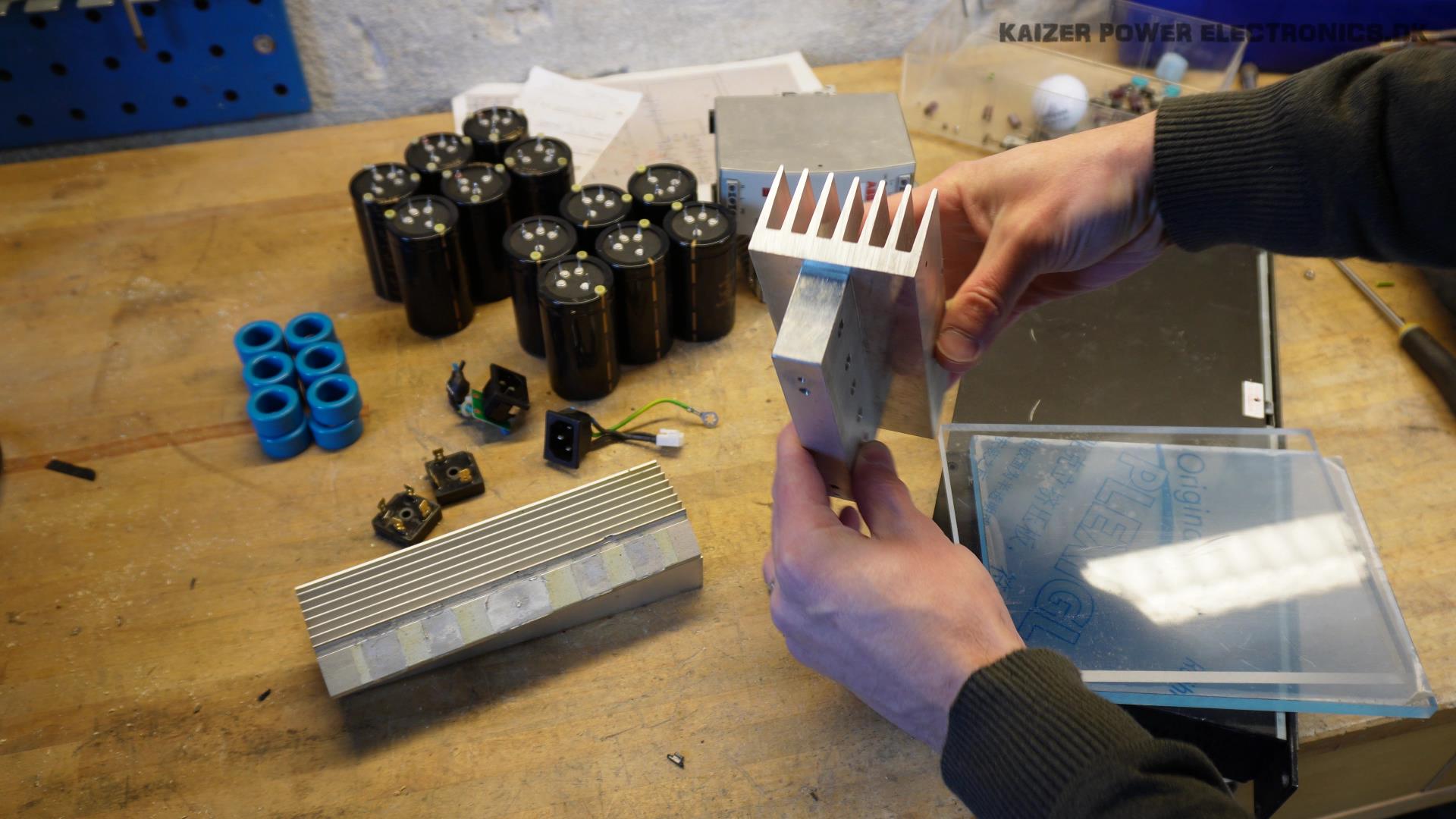
The primary goal of this video, is to find the components needed to build the DRSSTC design that was done in 10’ish minutes. The parts are either bought online, like the printed circuit boards, primary / secondary coil and topload. Other parts are found from my boxes of teardown / recycled materials, like the IGBTs, rectifiers, connectors, electrolytic capacitors and heat sinks.
To learn much more about Tesla coils, DRSSTC topology or see other reference designs of Tesla coils, check out all the different models I have constructed!
DRSSTC Components
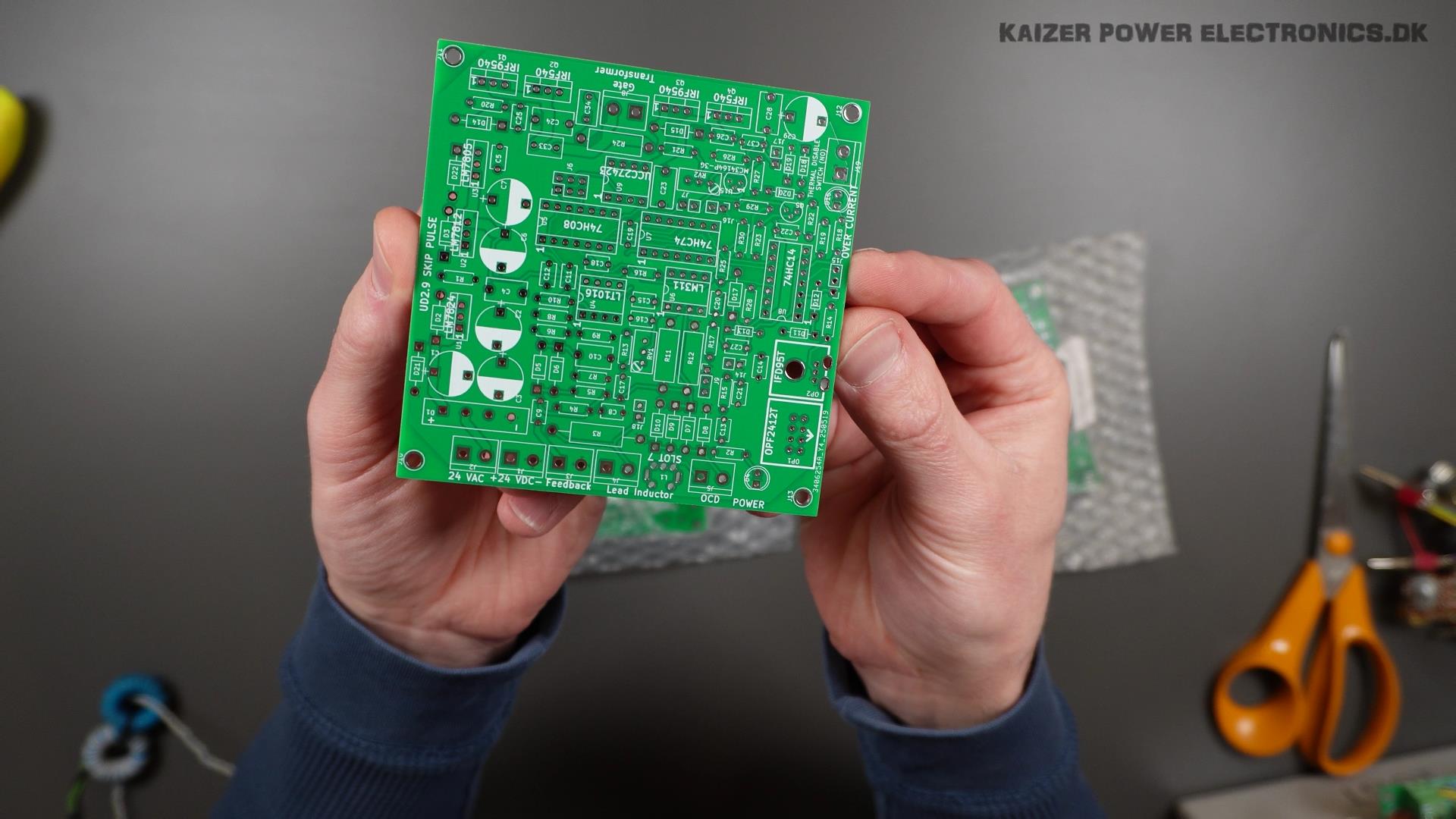
The drivers and interrupters printed circuit boards were ordered from a PCB manufacturer, by using the free gerber files in the DRSSTC PCB package. Quality is very good. Silkscreen has no errors or missing prints. Feed-through sticking between layers is perfect as well.
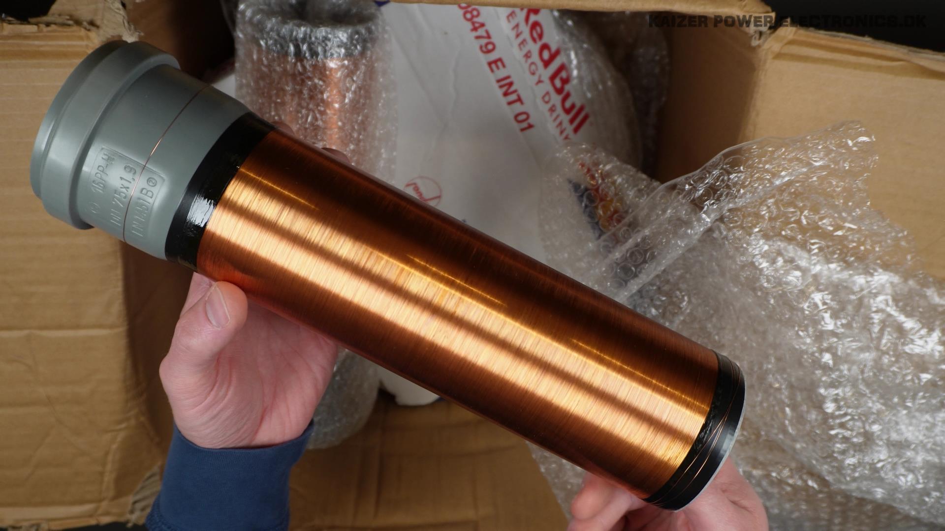
The secondary coils do feel a bit thin, with only two layers of thin varnish. It is not a thick layer of heavy flowing polyurethane, feels like its spray on varnish. The wire is secured in both ends with electrical tape, which makes no difference for operation, but does not look great. I did not try out the mounting set and topload holder yet.
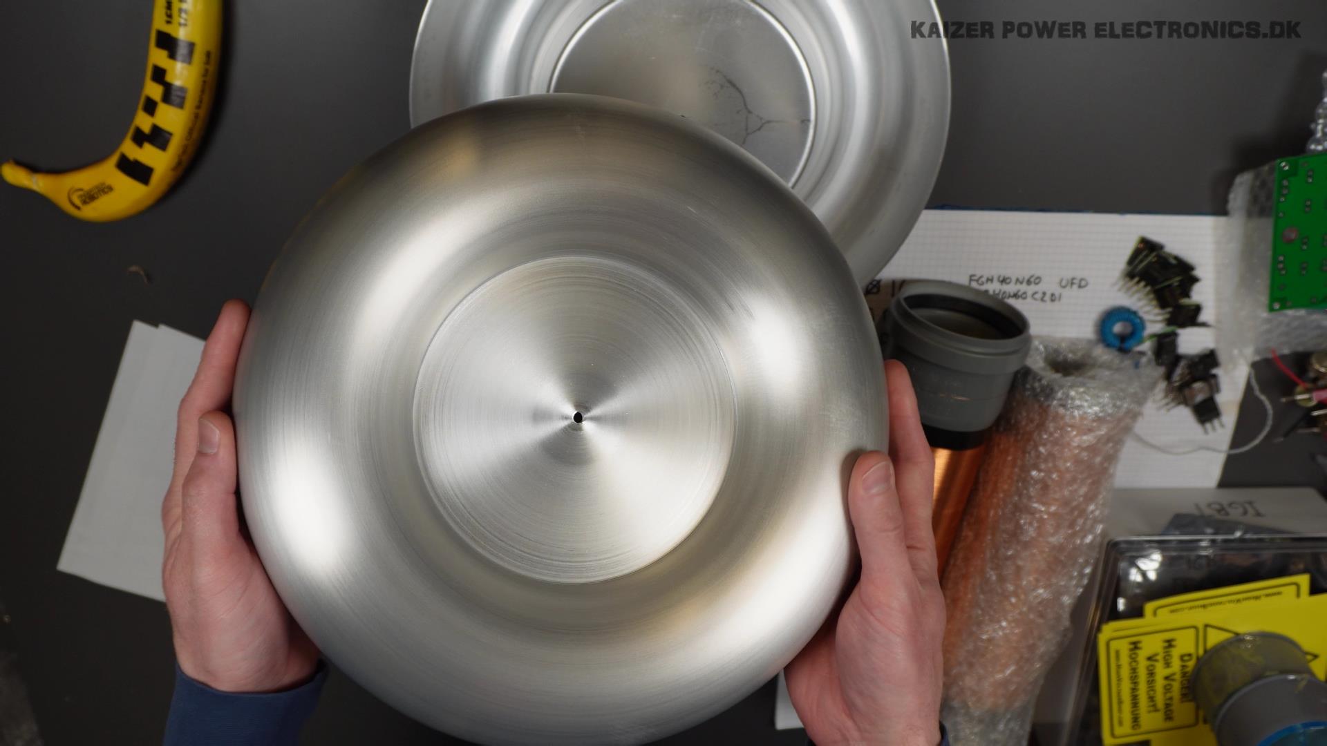
The toploads are very high quality! Very thick material, so very sturdy and resistant to bumps and dents. There is however only the center hole to make it completely round, it can easily skew a bit if a too small screw is used, or the two parts are pushed opposite directions.
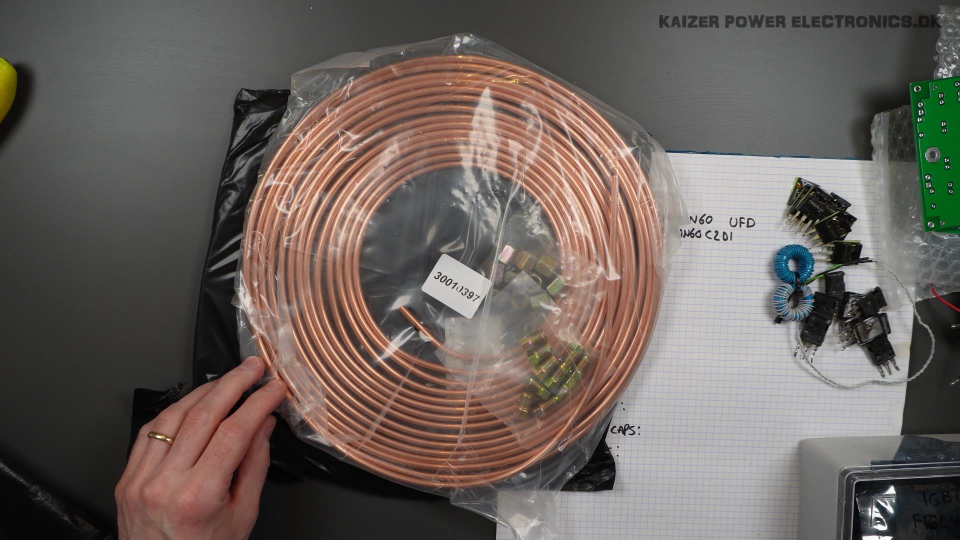
For the primary coil, the brake line copper tube is perfect for this sized Tesla coil. Its 3/16″ diameter (4.76 mm) has all the advantages of the large copper tubing, like being hollow, so skin effect is much smaller, than if we used solid wire. Normally solid wire would easily be used in a coil of this size.
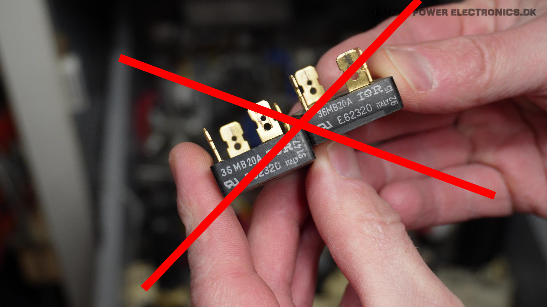
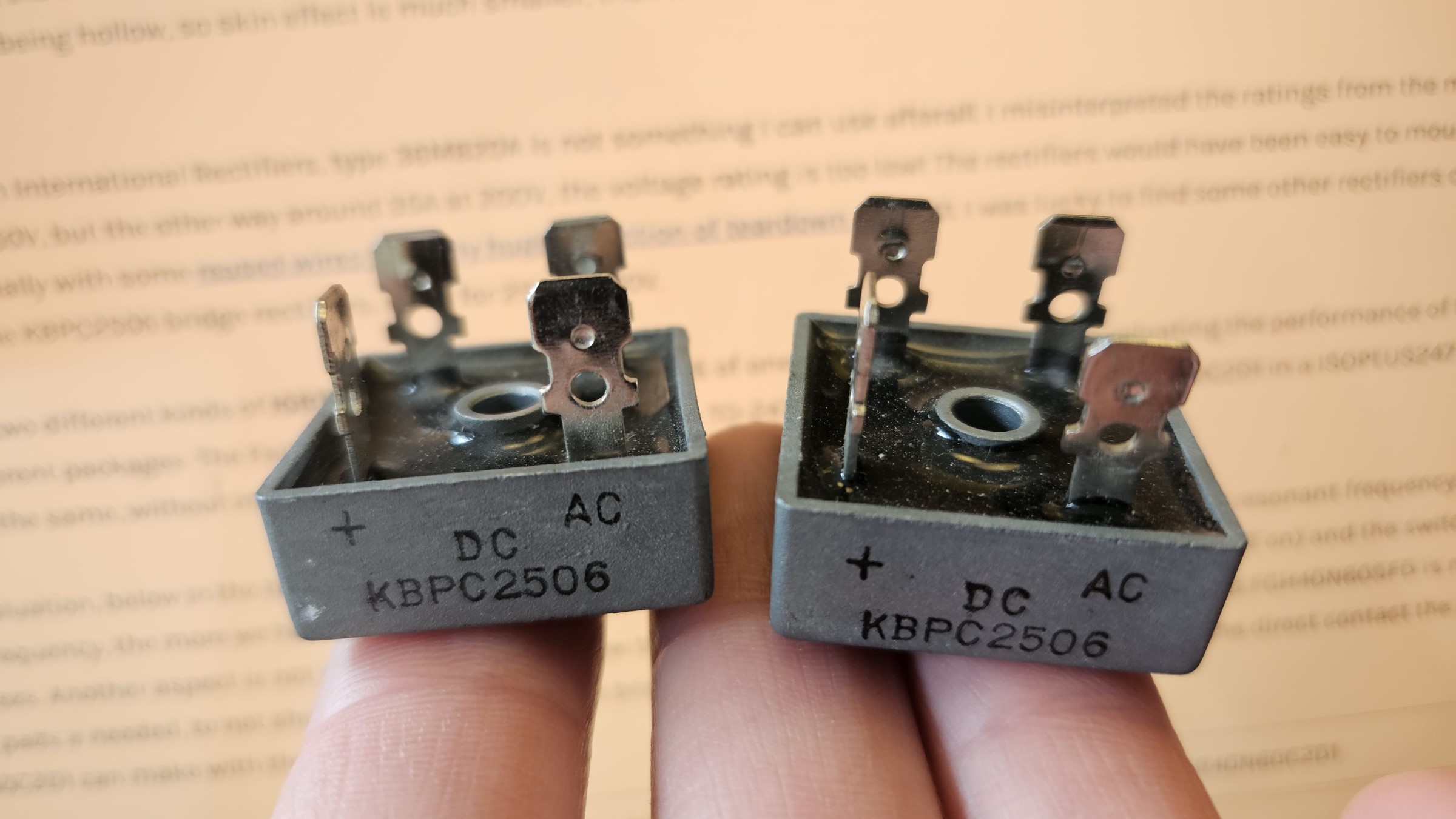
The rectifiers from International Rectifiers, type 36MB20A is not something I can use afterall. I misinterpreted the ratings from the model name, it was not 20A at 350V, but the other way around 35A at 200V, the voltage rating is too low! The rectifiers would have been easy to mount with cable shoe legs, especially with some reused wires from my huge collection of teardown wires :D. I was lucky to find some other rectifiers of the same package type, the KBPC2506 bridge rectifiers, rated for 25A at 600V.
I chose to use two different kinds of IGBTs, mostly due to not having 16 of one kind. This is perfect for evaluating the performance of the “same” rated die in two different packages. The Fairchild FGH40N60SFD comes in a TO-247 package and the Ixys IXGR40N60C2D1 in a ISOPLUS247 package, which is essentially the same, without mounting hole.
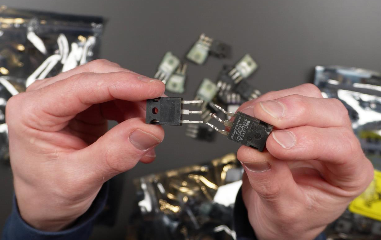
From the evaluation, below in the table, my verdict is that the Ixys IXGR40N60C2D1 is better suited for a 300 kHz resonant frequency. The higher switching frequency, the more we have to pay attention to gate charge (how much energy we need to drive the IGBT on) and the switching speeds/losses. Another aspect is not just losses, but also how to dissipate that energy. The flange of the Fairchild FGH40N60SFD is not isolated, so insulating pads a needed, to not short circuit the legs of the bridge. This makes power dissipation worse than the direct contact the Ixys IXGR40N60C2D1 can make with the heat sink.
| Fairchild FGH40N60SFD | Ixys IXGR40N60C2D1 | |
| Flange | Collector potential | Isolated |
| Saturation Voltage VCE(sat) | 2.3 V | 2.7 V |
| Pulsed Current ICM @ 25 oC | 120 A | 200 A |
| Maximum Power Dissipation PD @ 25 oC | 290 W | 170 W |
| Gate Charge QC | 120 nC | 95 nC |
| Turn-On Time td(on) | 24 ns | 18 ns |
| Rise Time tr | 43 ns | 20 ns |
| Turn-Off Time td(off) | 120 ns | 130 ns |
| Fall Time tf | 30 ns | 80 ns |
| Turn-on Switching Losses | 1.14 mJ | 0.6 mJ |
| Turn-off Switching Losses | 0.48 mJ | 0.5 mJ |
For the current transformers (CT) and gate drive transformers (GDT) the same type and size ring cores can usually be used. I chose a Epcos B64290L0647X830 which is made from N30 material with a 5630 AL value. Most cores / materials with a AL value around 5000 is suitable.

The heat sinks is two different types. I think that the flat heat sink for the ISOPLUS247 package is the original heat sink from the Ixys IXGR40N60C2D1 that was used in a induction stove / cooker. The other type is in two parts, a block for the IGBT mounting and a part with fins to go on top of that.
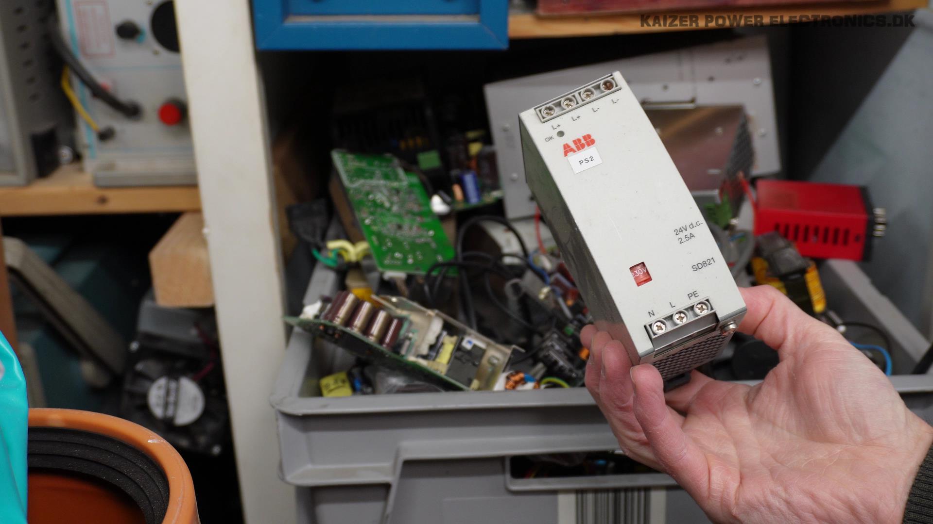
The power supply for the driver, I chose a ABB SD821, 24 VDC at 2.5 A industrial power supply, with 230 VAC input. It just takes up less space than a transformer (also I did not have any suitable transformers), and I can skip having the rectifier / capacitors on the driver board itself.
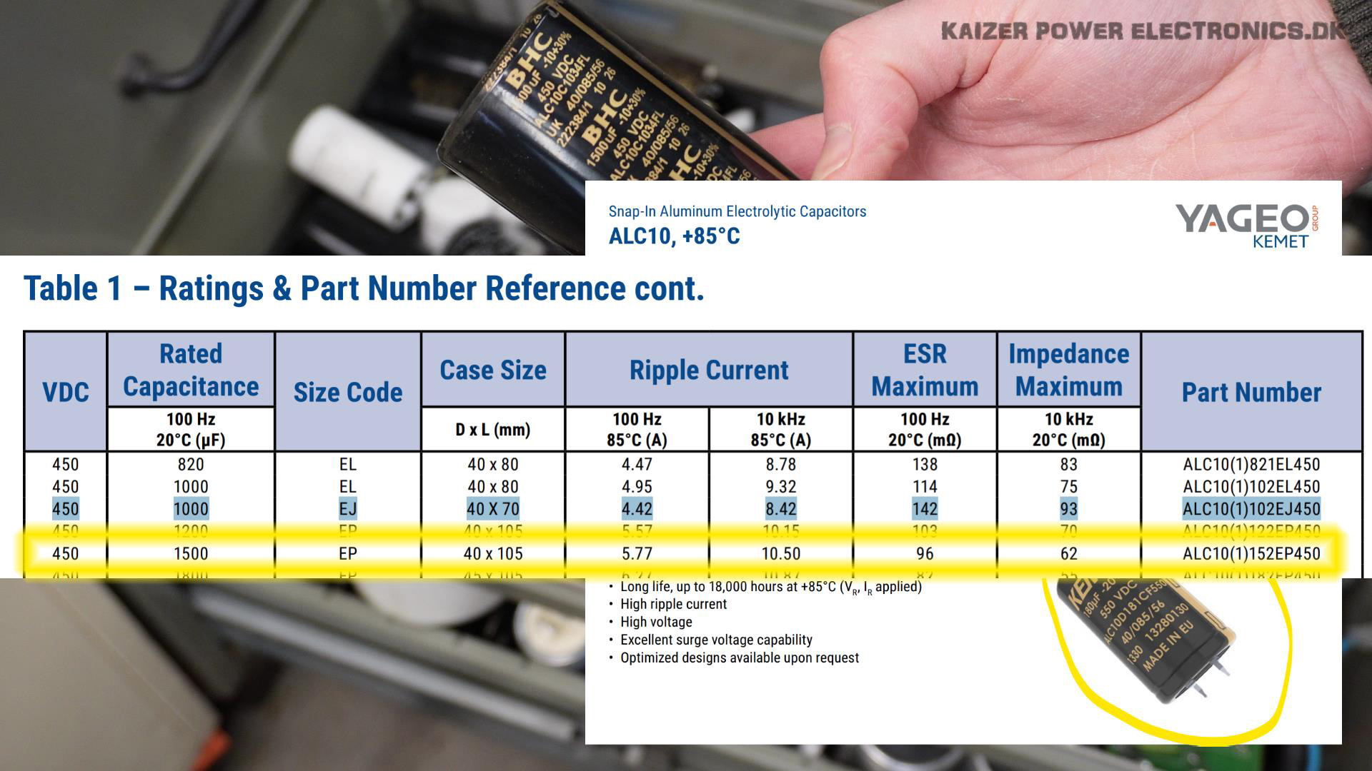
6x 1500 uF Epcos ALC10 electrolytic capacitors in parallel, is used to make a 9000 uF at 450 VDC bank for the DC bus capacitance. It is able to deliver high peak currents from the 6 capacitors in parallel and withstand around 60 A ripple current.