In this video I rebuild one of the Tesla coils with IGBT bricks instead of TO-247 devices. I am done with small transistors that can not outlive my abuse. With the new 2MBI50N-120 based inverter we can once again do the static load test and adjust phase lead compensation on the Tesla coil.
This is the 6th article / video in the series of designing and building a DRSSTC Tesla coil from scratch, with focus on being easy and cheap, for you to replicate. You can find the previous information in these articles:
- Designing A Complete DRSSTC Tesla Coil In 10 Minutes
- Building the 10 Minute DRSSTC Part 1: Finding the Components
- Building the 10 Minute DRSSTC Part 2: Construction and Assembly
- Testing the 10 Minute DRSSTC Part 1: UD2.9 Driver and DC Bus Capacitors
- Rebuilding the 10 Minute Design DRSSTC, Static Test and Phase Lead Adjustment
Changing from TO-247 IGBTs to 2MBI50N-120 brick IGBTs
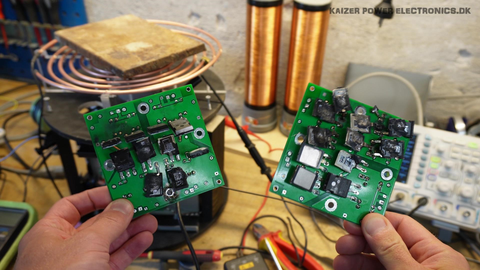
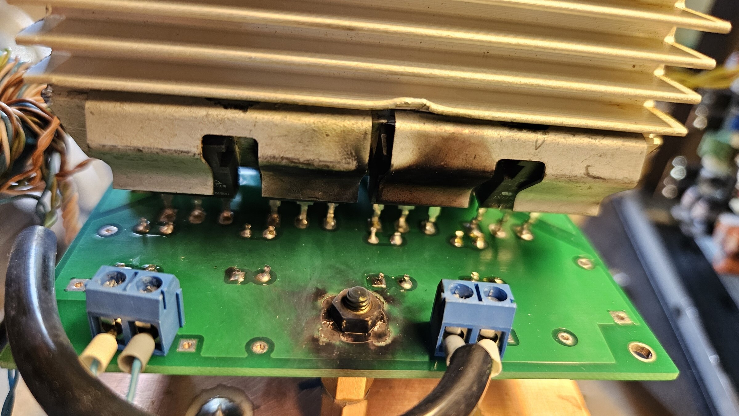
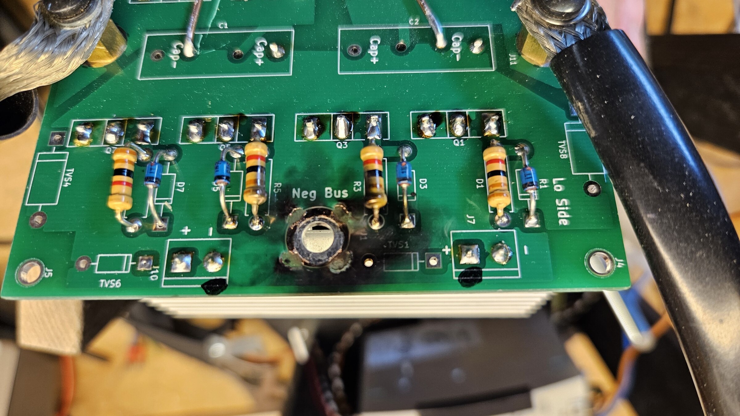
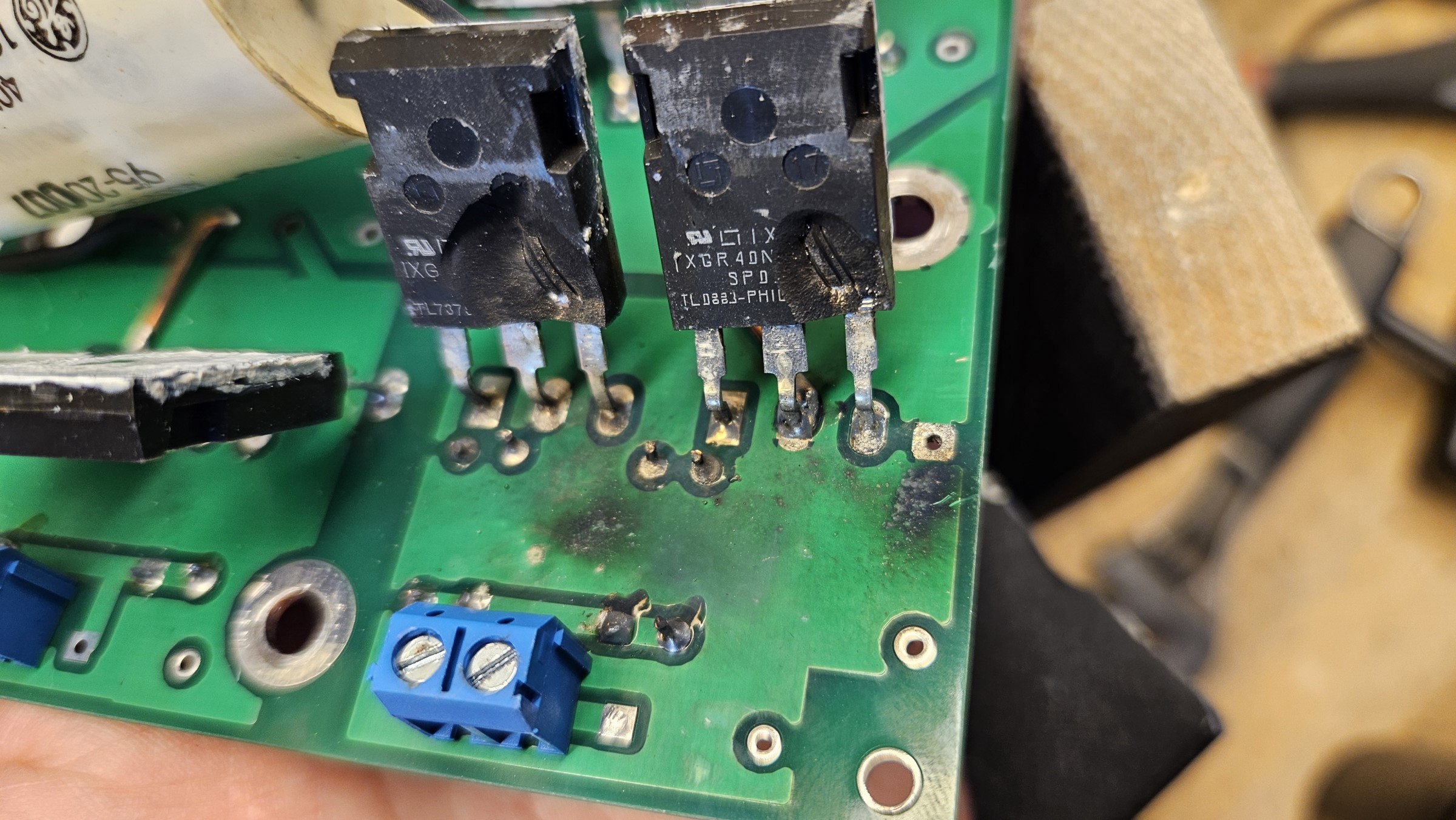
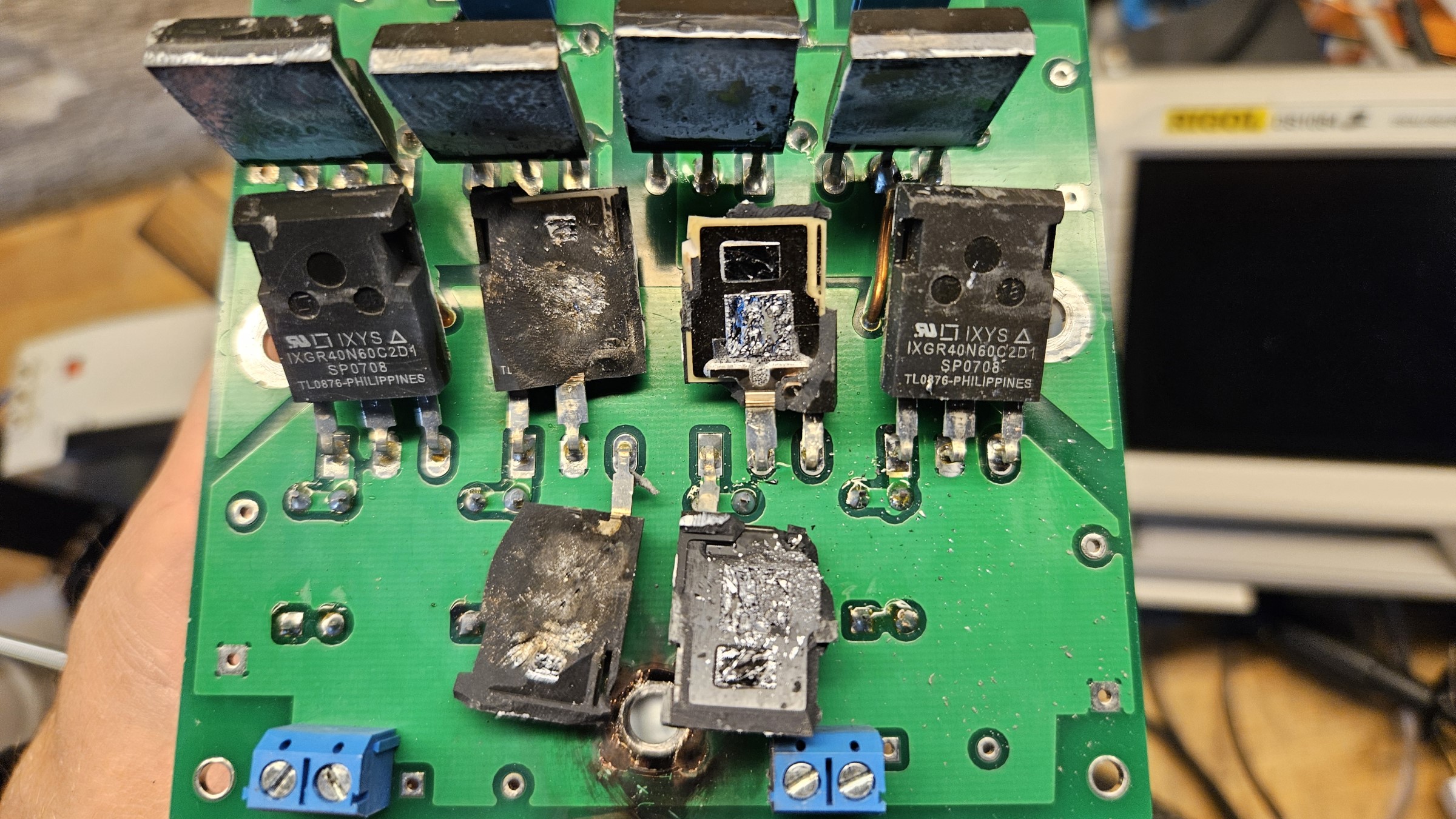
I pushed the IXGR40N60C2D1 IGBT based PCB full-bridge way too hard. I do not think it was too hard, with parallel IGBTs it should have been able to handle 400+ A peak in the primary circuit. Nonetheless it did not like it and exploded violently. This time with TO-247 package sharpnel flying around in the work shop, always wear glasses and ear defenders 🙂 At this point I remembered giving up on TO-247 devices in DRSSTCs, that was about 10 years ago.
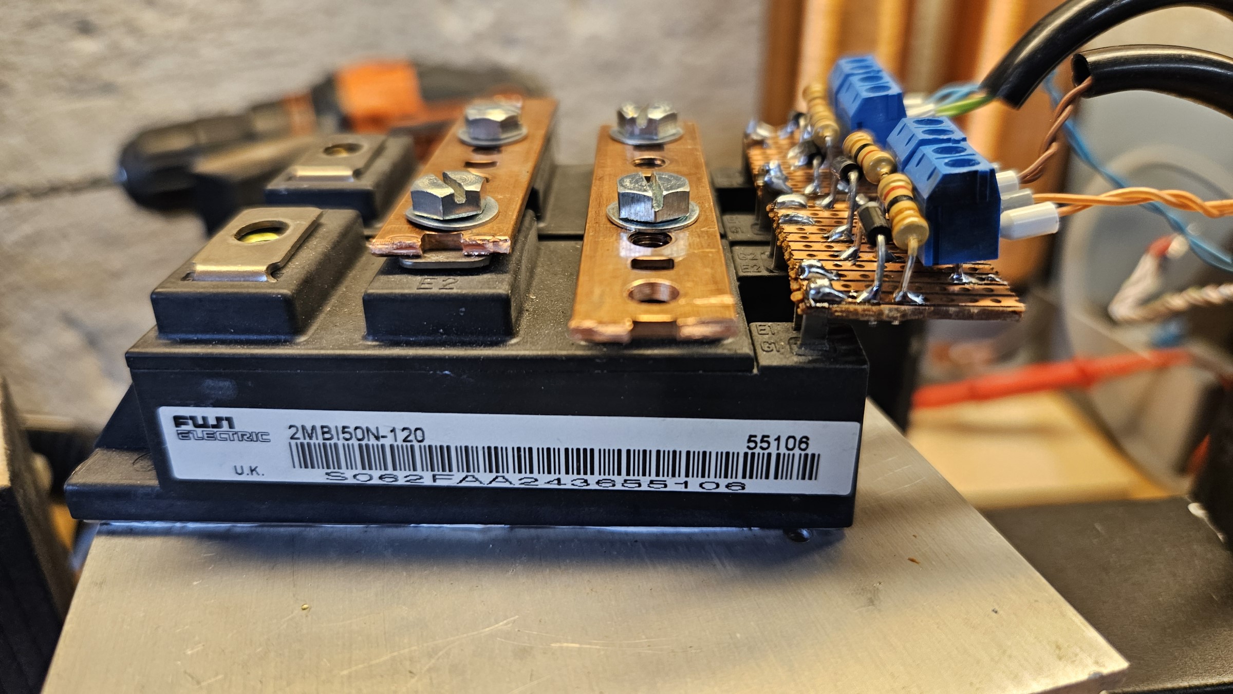
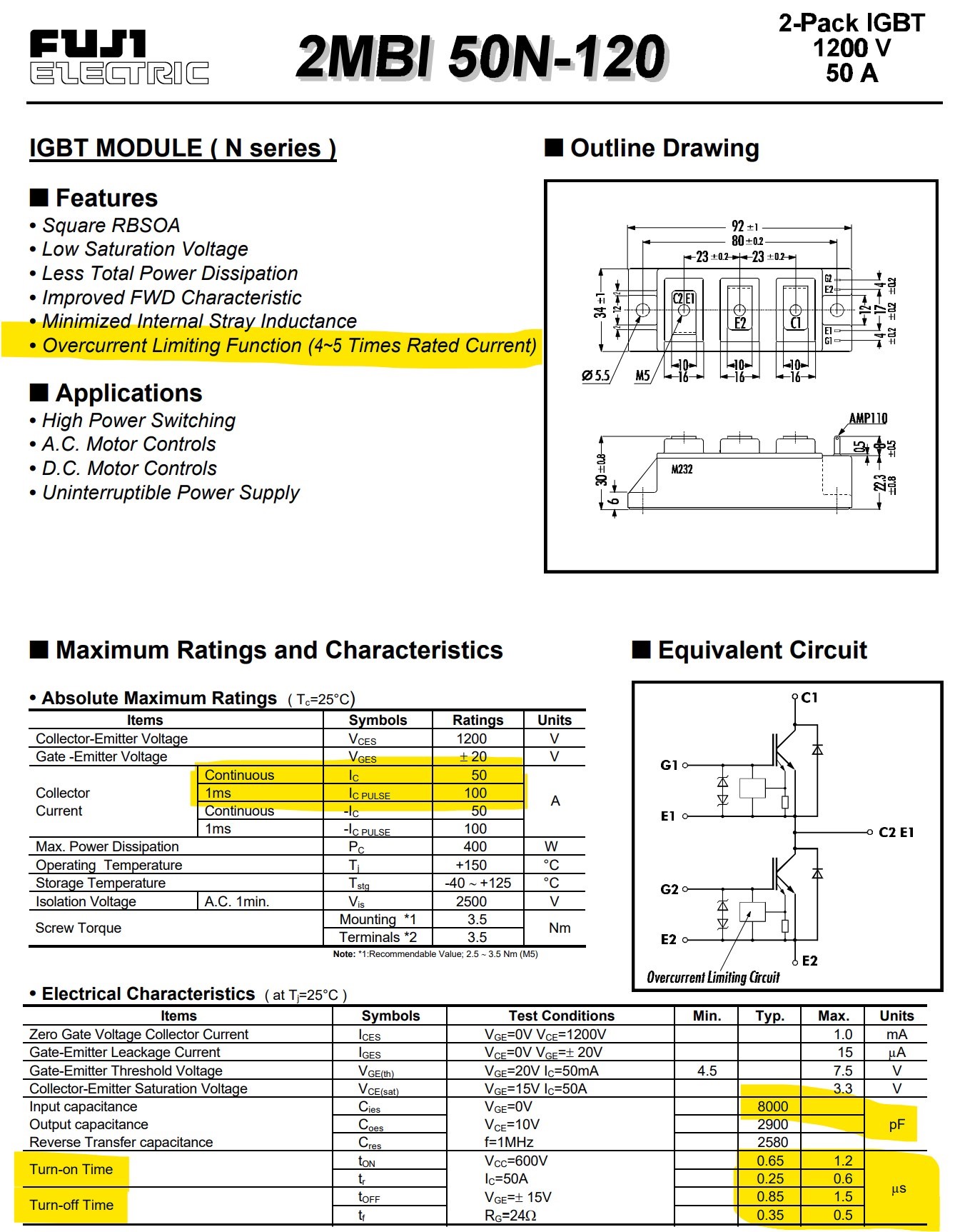
The new inverter full-bridge should be brick based and the smallest bricks I had in storage was Fuji 2MBI50N-120. These bricks are rated for 50 A at 1200 V, by the higher voltage rating, they will also have higher requirements to driving them (larger gate capacitance). This model has a built in current limiter at 4-5 times the rated current, we will have to challenge that statement in tests.
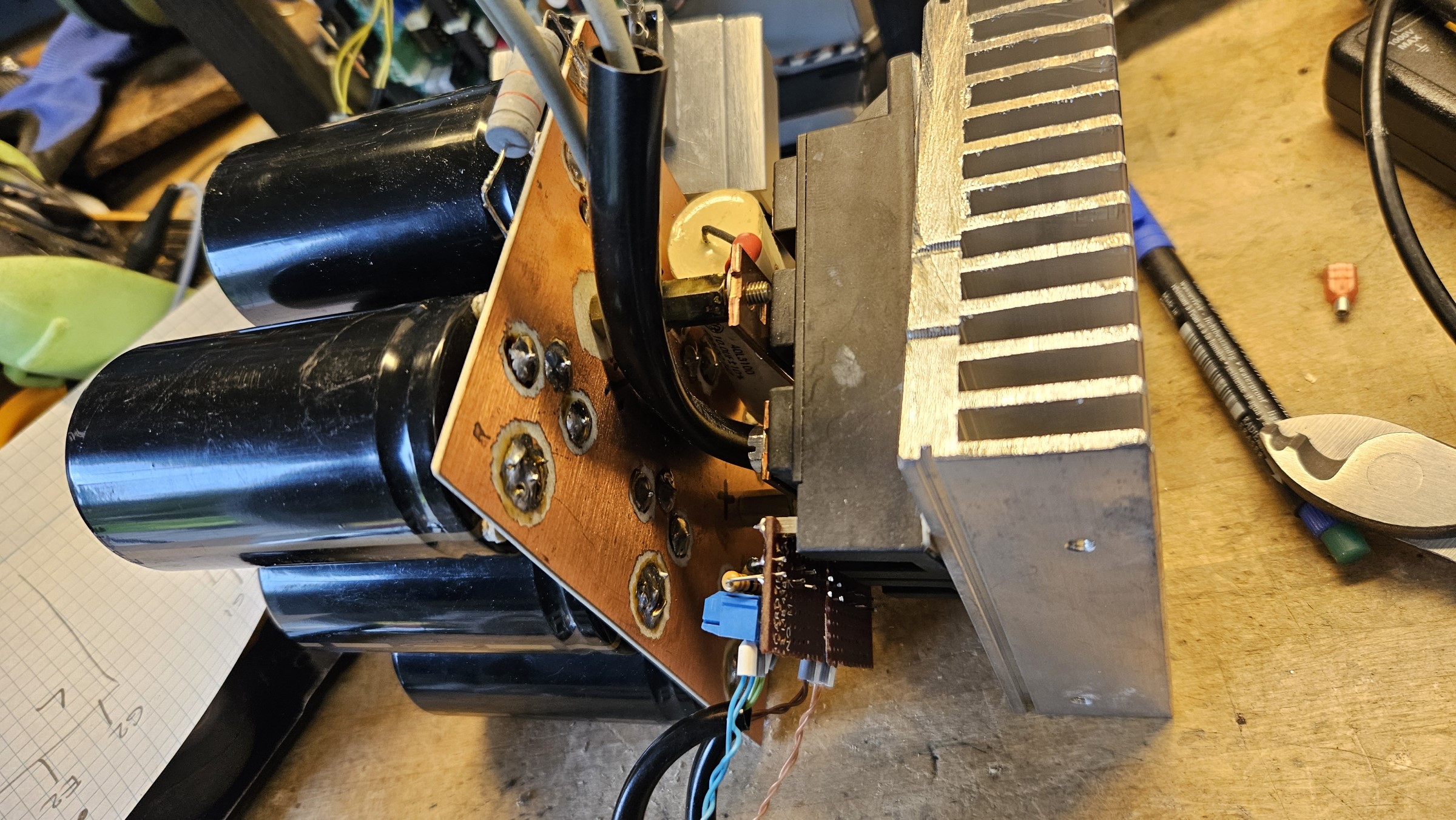
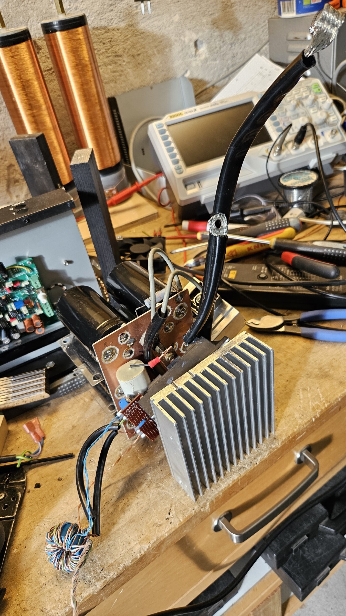
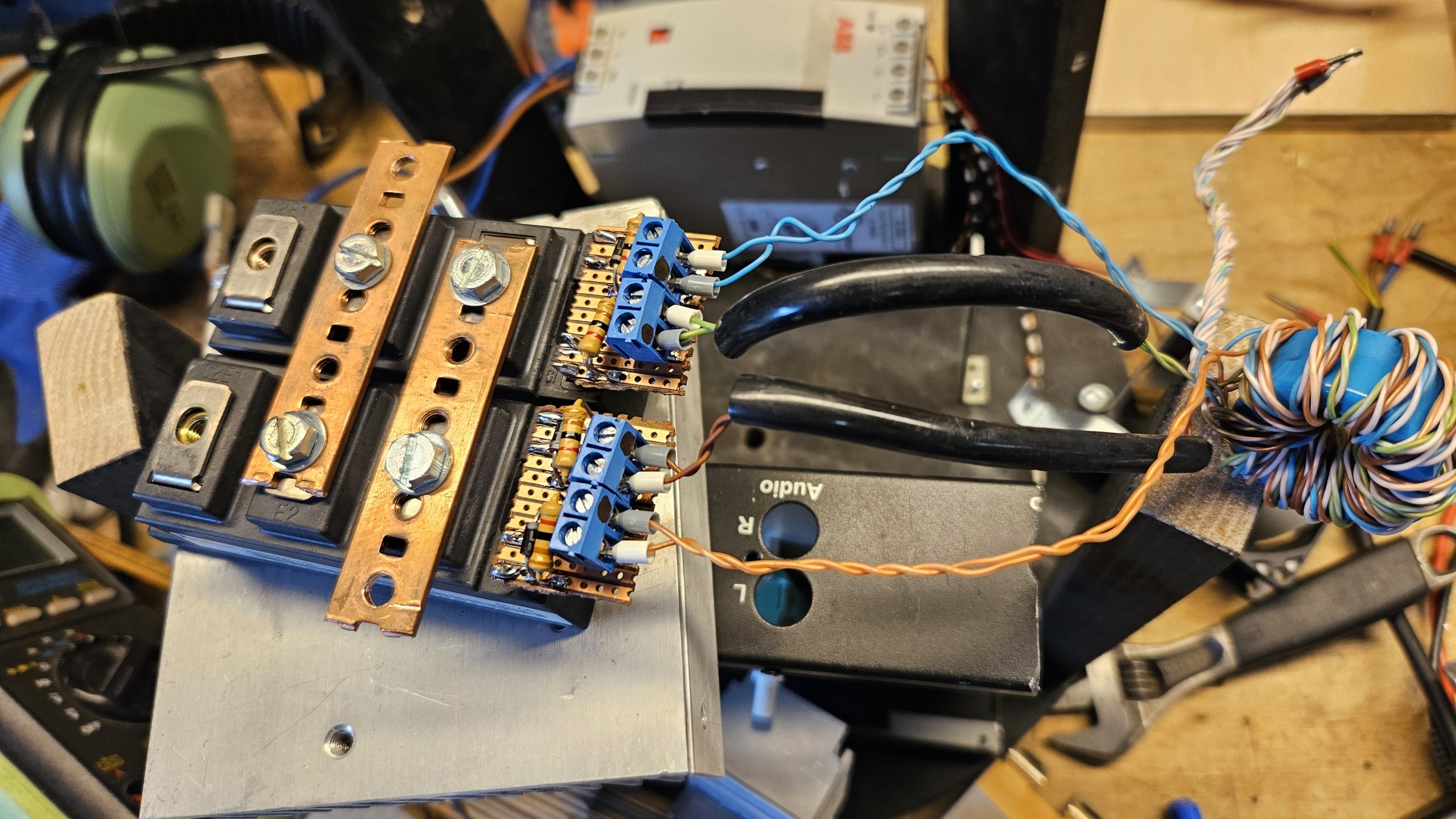
Building full-bridges with half-bridge IGBT bricks is easy. It is really as simple as two pieces of busbar, connecting each to positive and negative rail of the DC bus and the last two terminals are for the inverter output. I built this new bridge with prototype PCBs for the gate drive in a hour or so.
Phase Lead Adjustment and Pulse Skipping
Phase lead compensation needs to be re-adjusted with a new inverter. The 2MBI50N-1200 bricks are much slower at turning on and off, compared to the IXGR40N60C2D1 TO-247 IGBTs. They are only much slower on paper, in reality we are getting help from the resonant switching. The switching times given in a datasheet is for hardswitching, resonant inverters is softswitching and we are helped by the current crossing zero. I have described this softswitching speed behaviour in the IGBT part of the DRSSTC Design Manual.
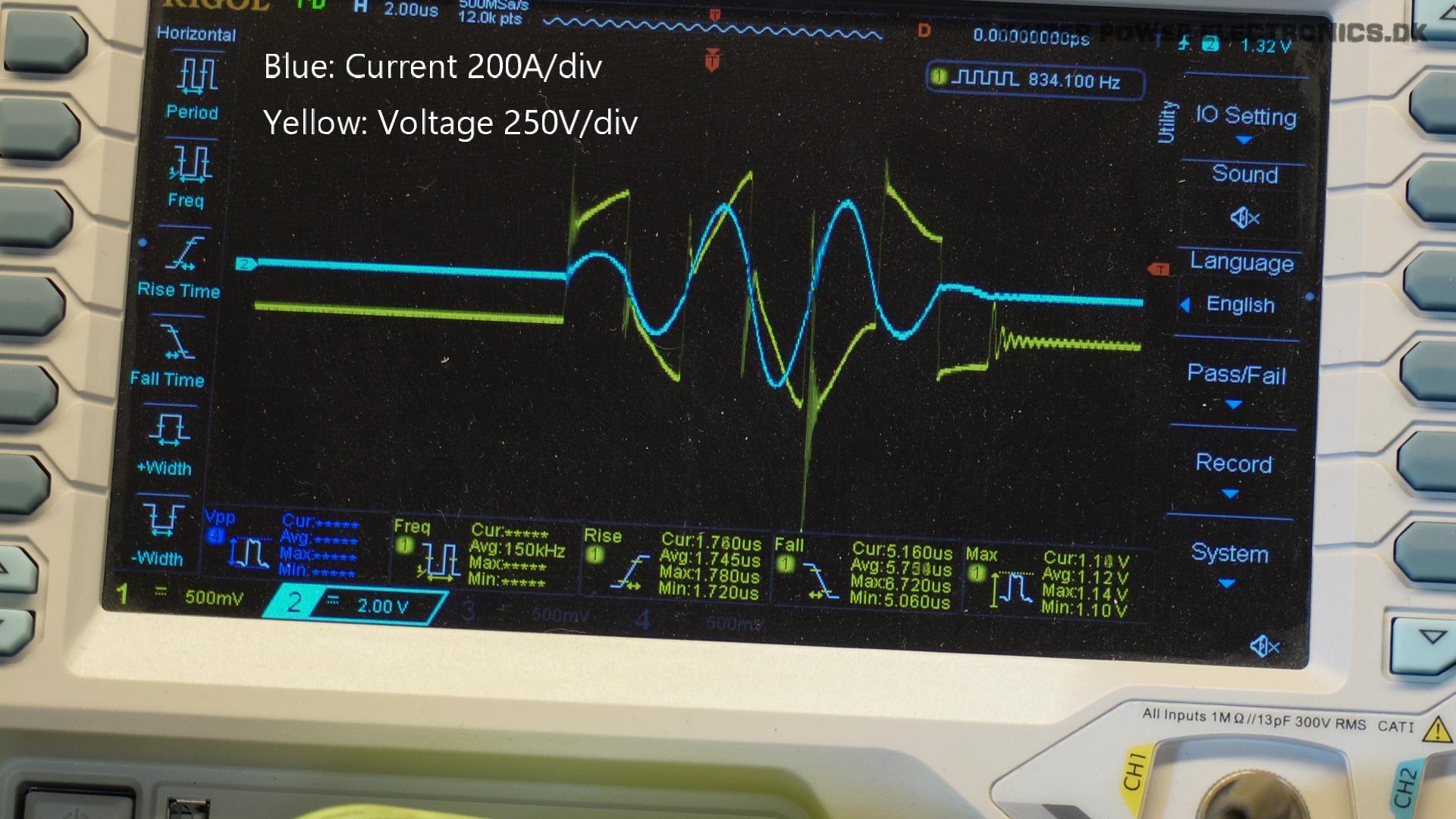
I first powered up the coil at 50 VDC and observed no oscillations. Powered the coil down again and changed driver GDT output polarity with the two jumpers on the driver. Afterwards coil would oscillate and first adjustments were made at 100 VDC bus. The phase lead adjustment is done at full DC bus voltage of 320 VDC. See the huge switching spikes before phase lead adjustment, especially the turn-off event in the middle generates a extreme negative spike and oscillations.
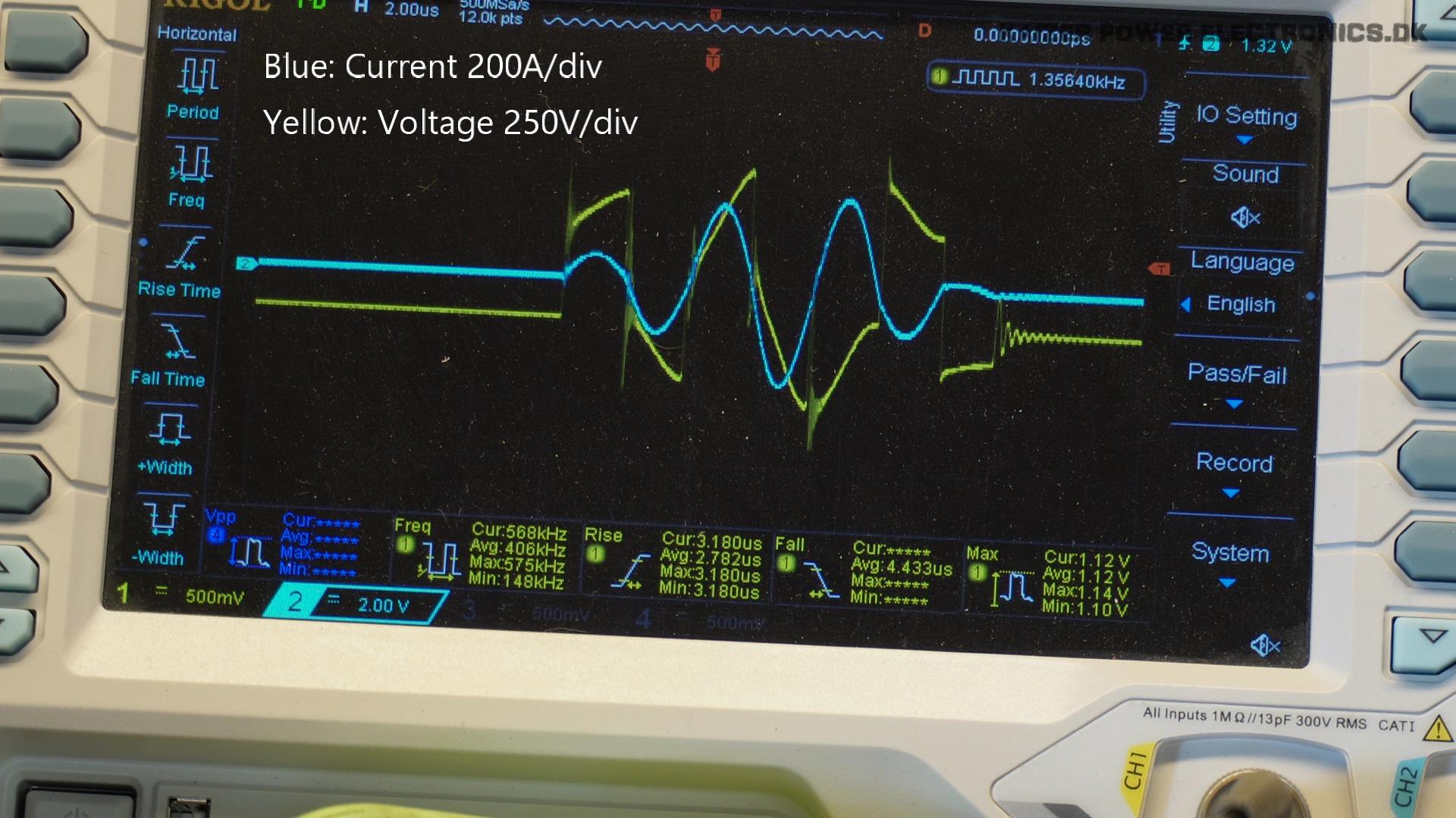
The adjusted phase lead waveforms shows that it is not perfect, but we have overall lessened the magnitudes of the switching spikes. The 1200 V rating of the IGBT brick, makes it less of a problem compared to the previous 600 V rated TO-247 IGBTs.
If adjusting the inductance is not making any change to the waveform, maybe the inductor size or type is not suitable. To check your variable inductor, you can use this calculator I made for this purpose: https://kaizerpowerelectronics.dk/calculators/ud2-x-phase-lead-calculator/