Teardown of an O.J. Electronics 4 kW Variable Frequency Drive. A special frequency inverter drive build to sit directly on the back of the asynchronous motor. Power electronics and control is based on Infineon silicon parts with a Freescale MCU+DSP IC full of features directly designed for motor drives.
For more teardown videos, articles or if you just want to see what is inside industrial and complex technology. Check out the complete list of teardowns!
Piggyback Frequency Inverter
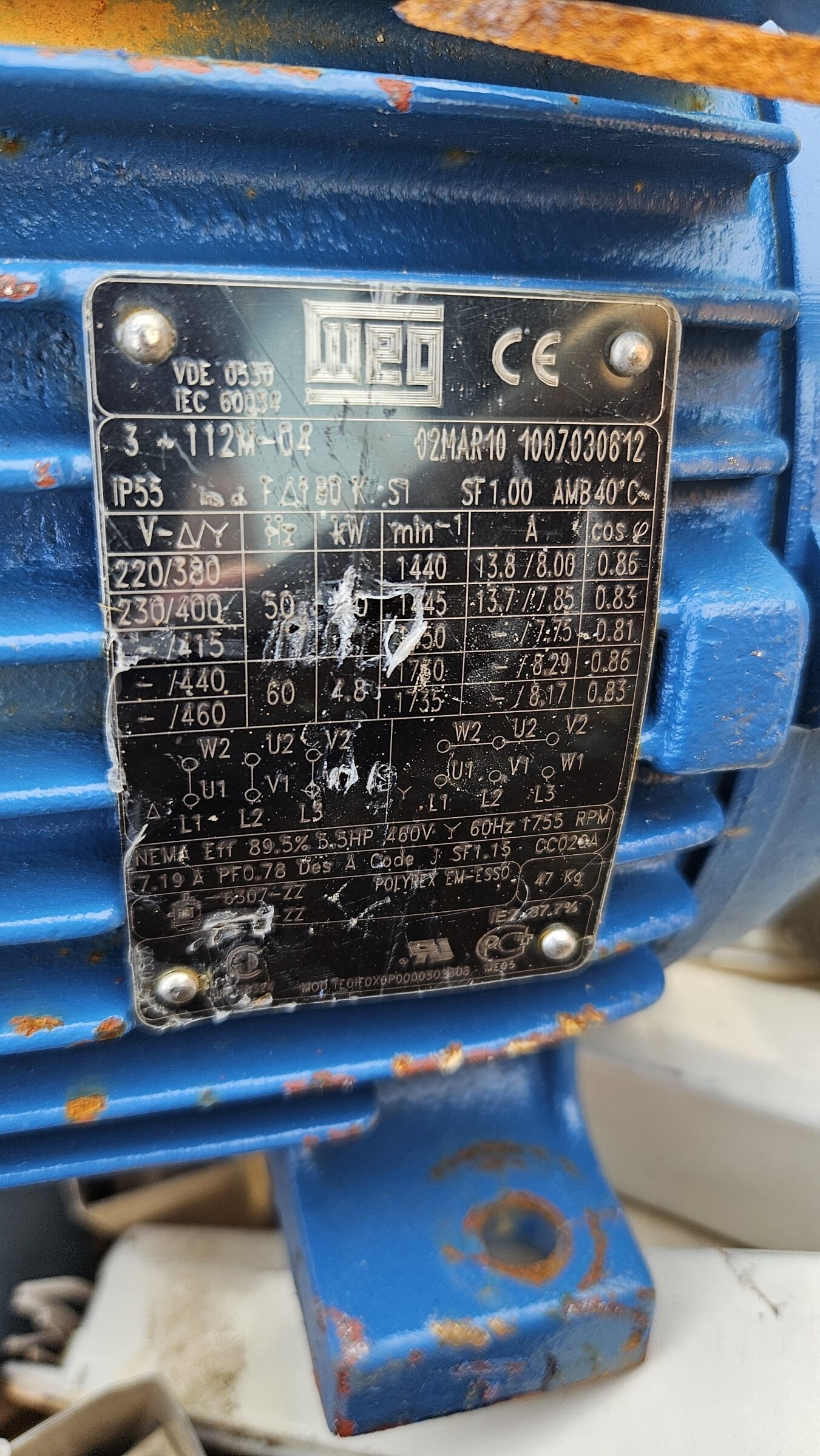
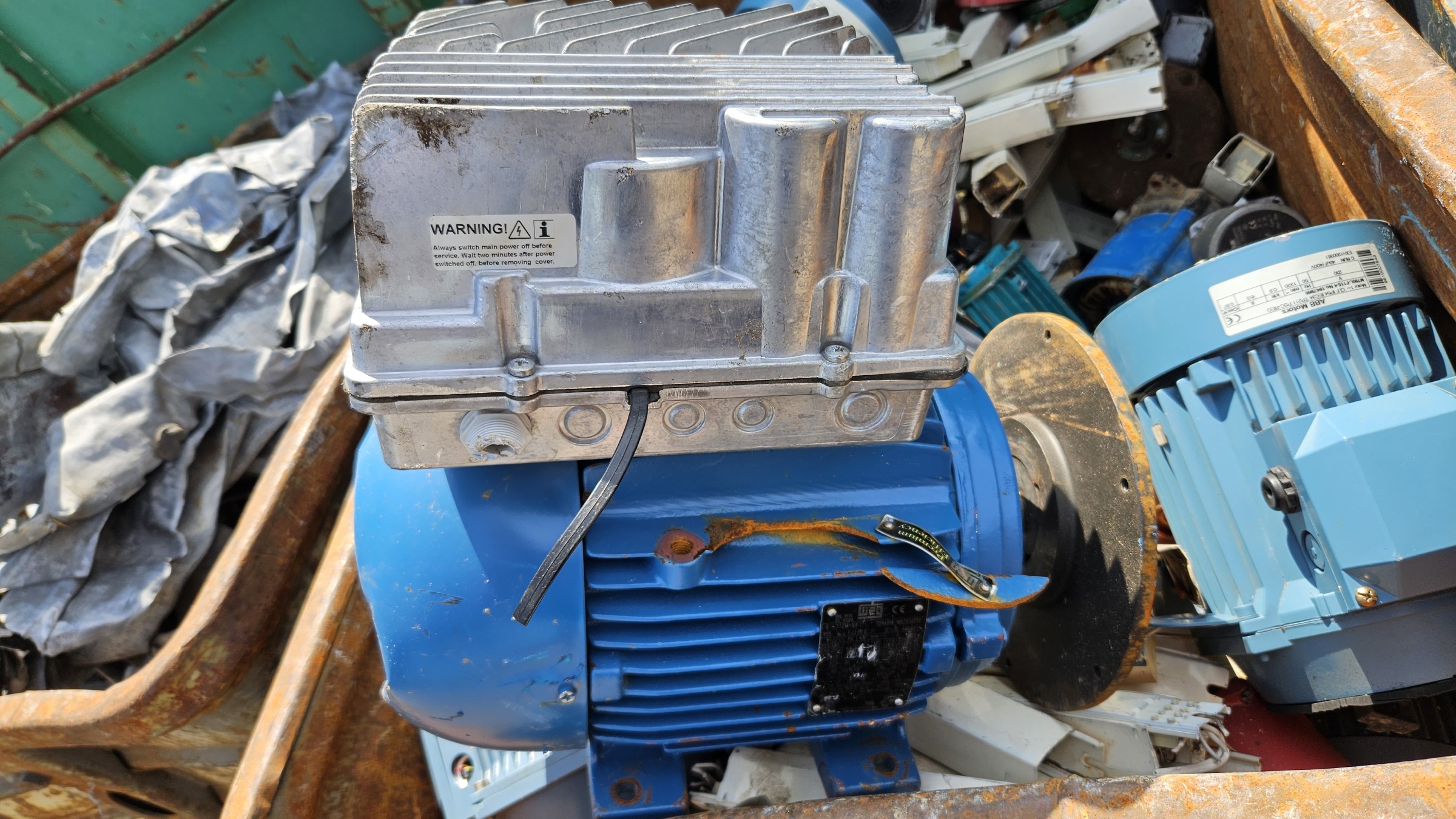
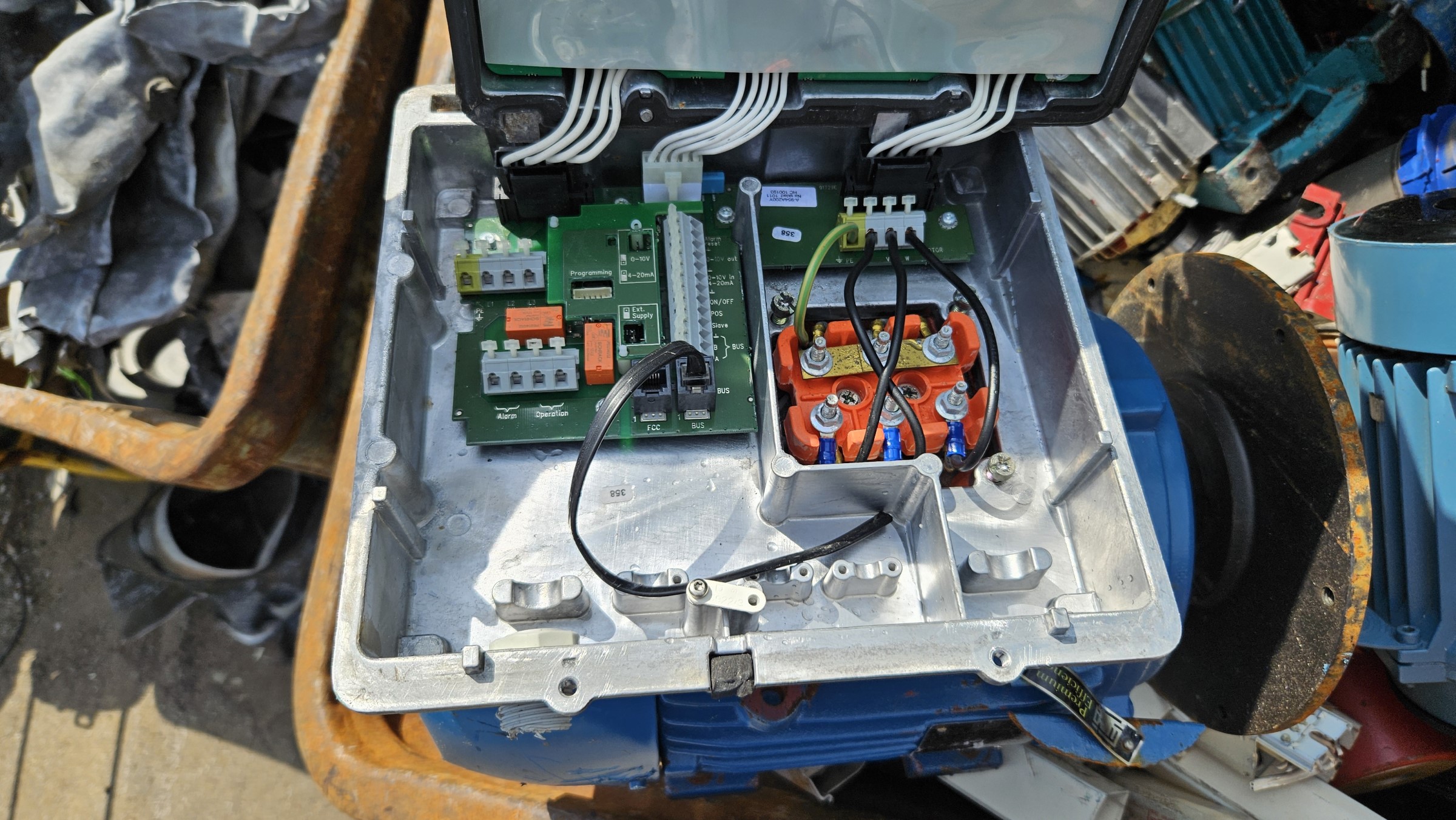
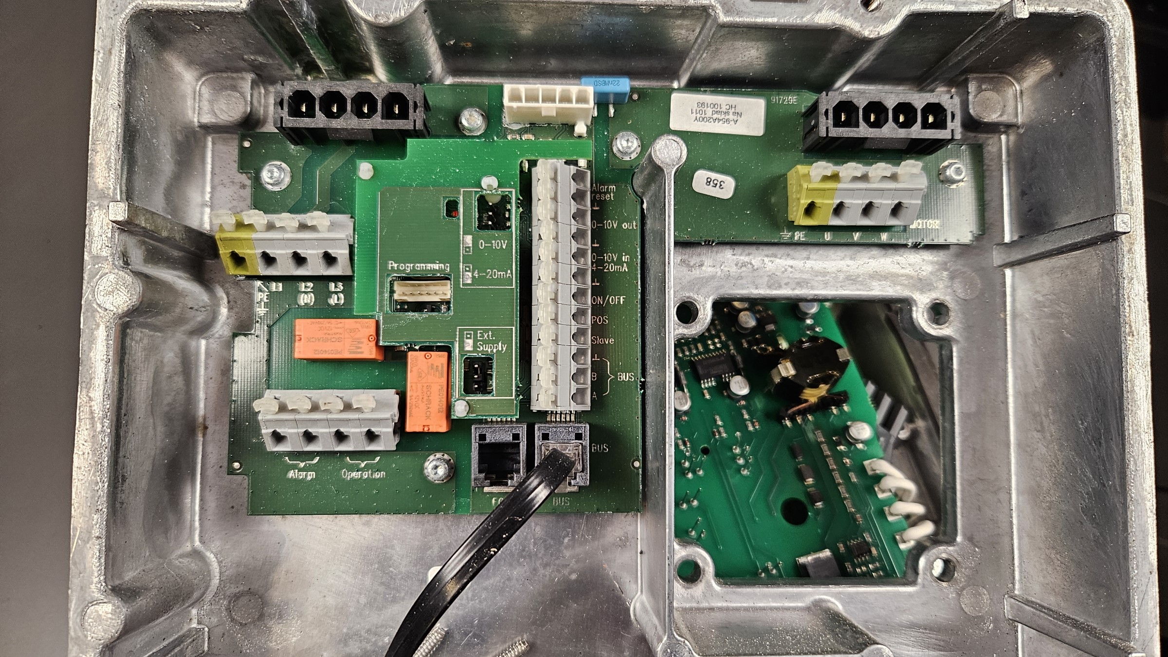
This O.J. Electronics FCB40 motor drive is designed to sit directly on the back of a 3-phase asynchronous motor. The square hole in the drive enclosure, fits around the motor connection block.
Frequency Inverter Power Electronics
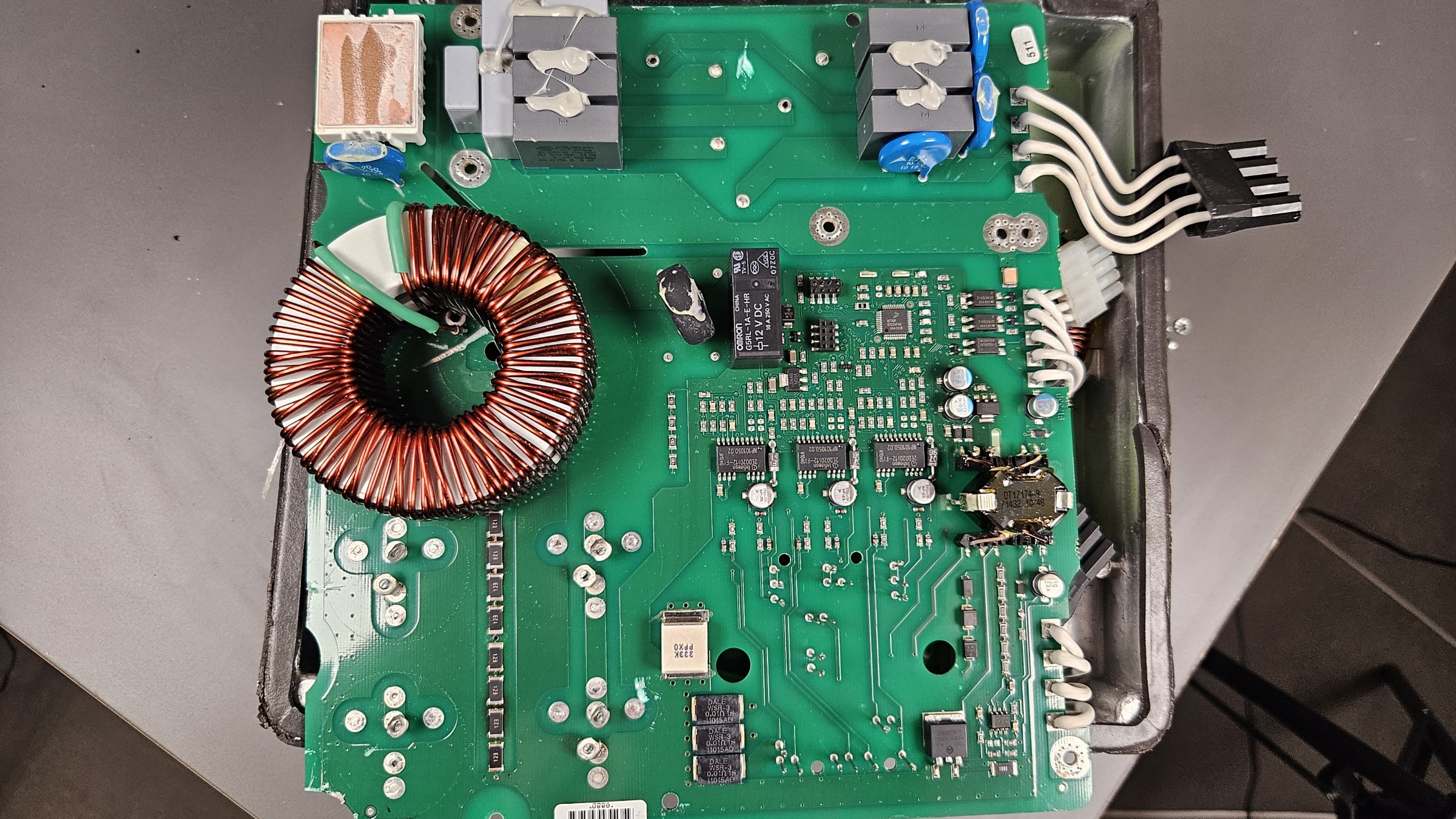
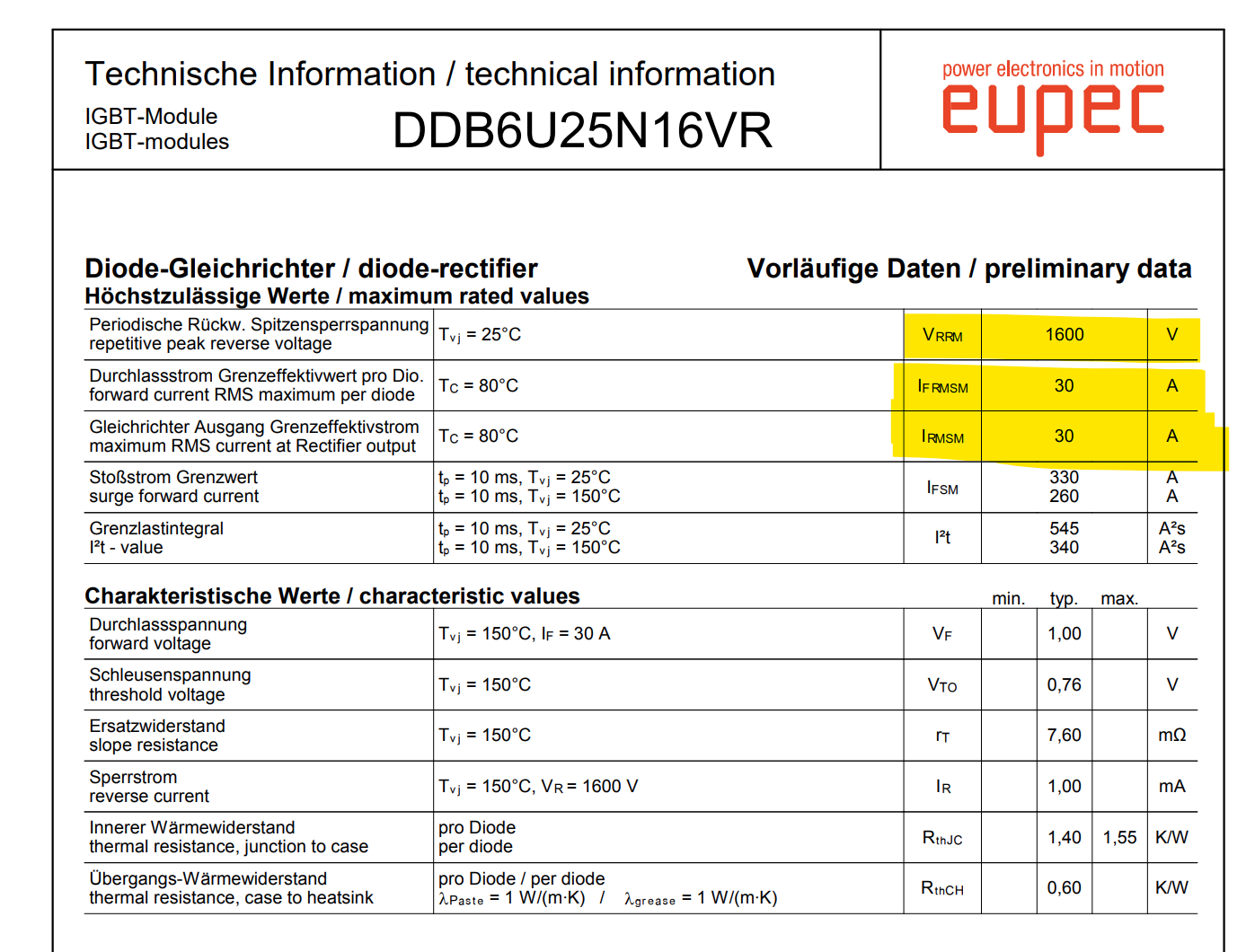
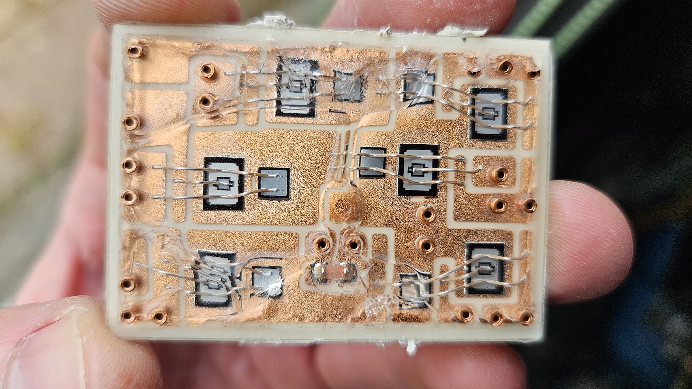
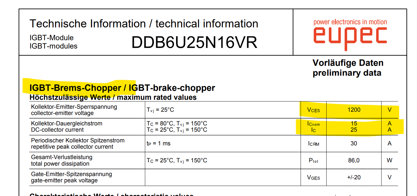
The mains input is filtered by MKP capacitors and MOVs. A 3 phase inductor sits between the first filter and a second MKP capacitor filter with 7 capacitors. The first silicon in the drive, is a double diode bridge module, an Eupec / Infineon DDB6U25N16. This is a 3-phase diode full-bridge rectifier, with a built-in IGBT brake chopper switch. This brake chopper IGBT does however not seem to be in use, as there is no drive circuitry for it.
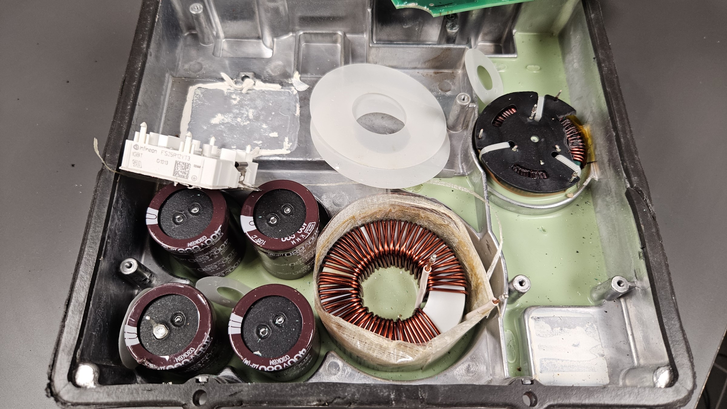
The DC bus part of the power supply consists of four electrolytic (450V 680uF) capacitors and a large double ring core inductor. The inductors and capacitors are all glued to the heat sink with a green compound for thermal coupling.
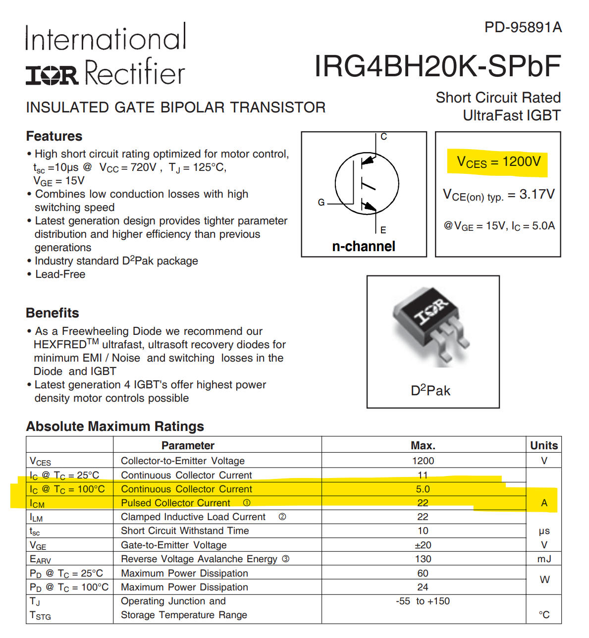
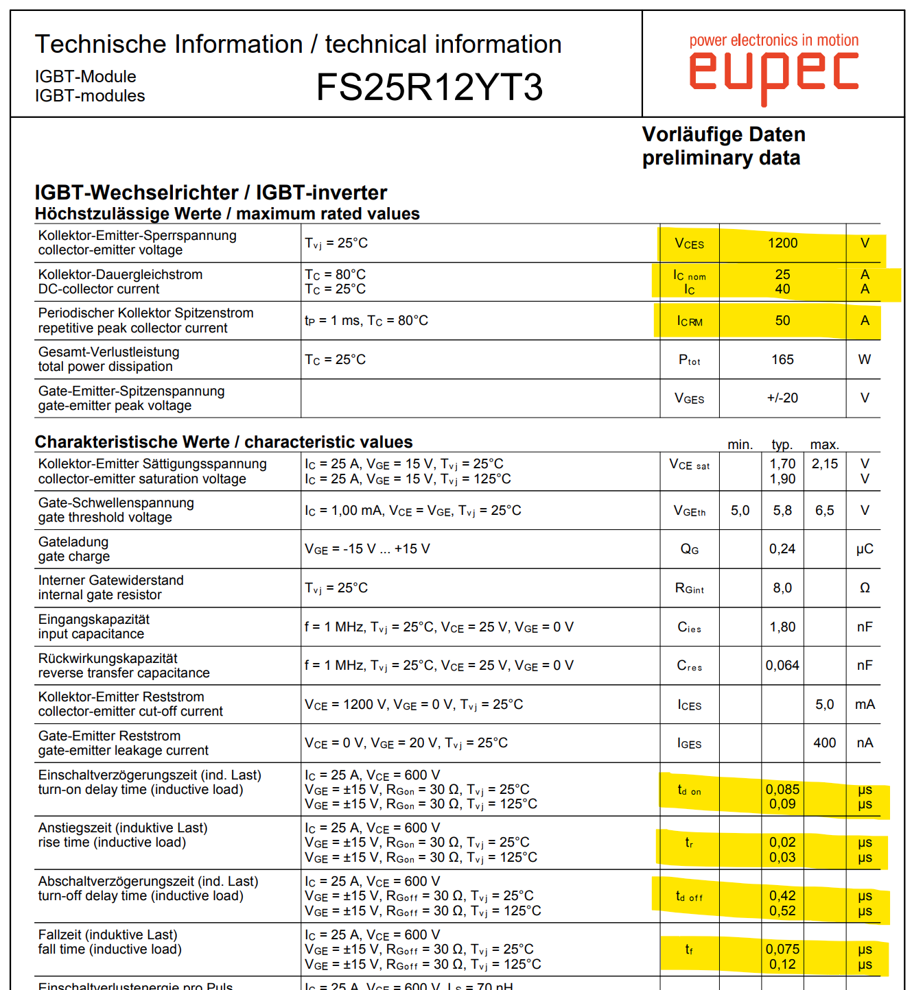
The output IGBT module is an Eupec / Infineon FS25R12YT3, a 3-phase full-bridge rated for 25A at 1200V. Pulsed rating is specified at 50A. At the output connector there is a International Rectifier IRG4BH20K IGBT, which corresponds to being the real brake chopper switch in this drive. There is a string of resistors for output voltage sensing and three 0.01 Ohm power resistors, to sense output current in each motor leg.
Frequency Inverter Control Electronics
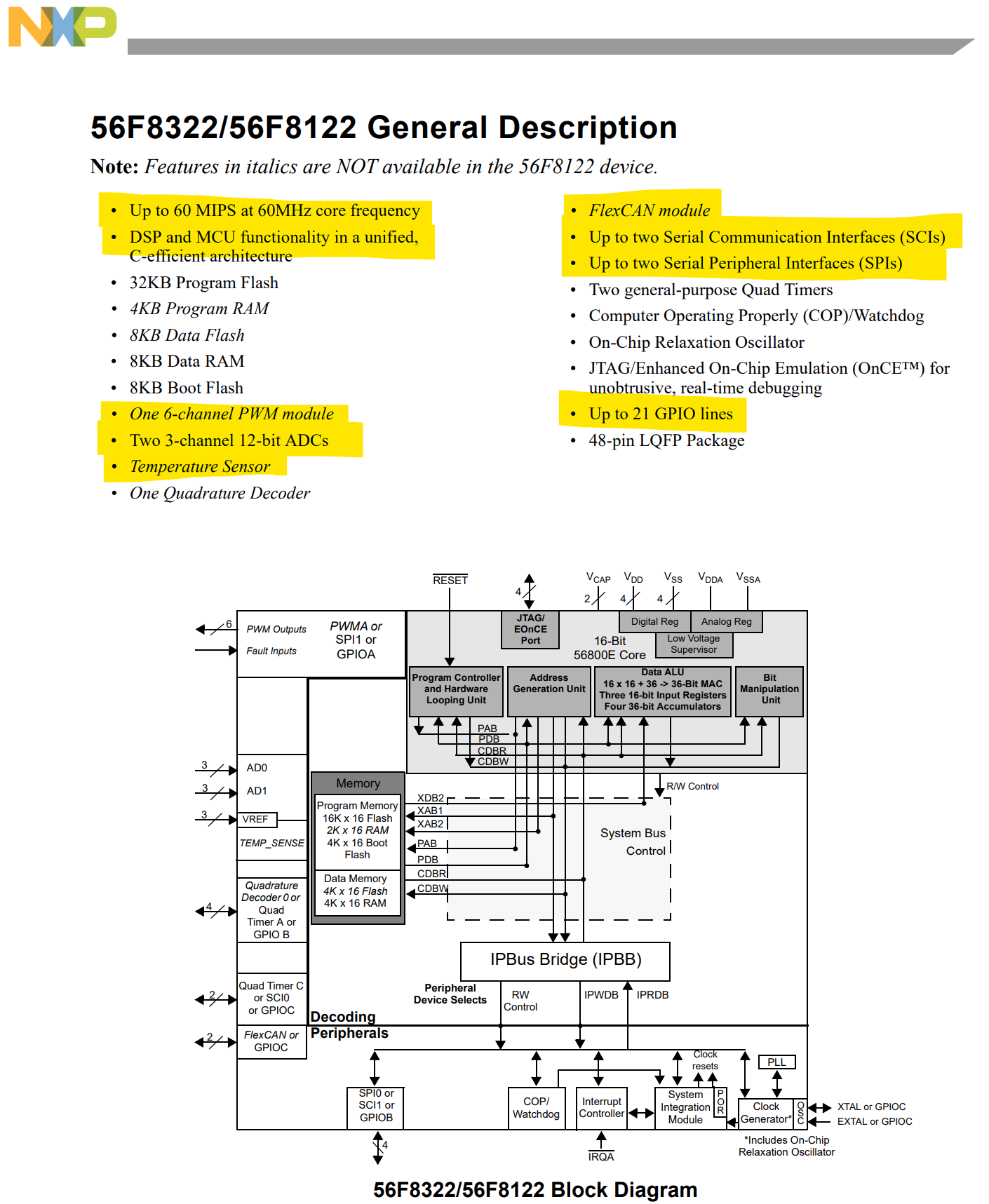
The main controller of the drive is a Freescale 56F8322 MCU/DSP IC. A general description of its features from the datasheet:
- Up to 60 MIPS at 60MHz core frequency
- DSP and MCU functionality in a unified, C-efficient architecture
- 32KB Program Flash, 4KB Program RAM, 8KB Data Flash, 8KB Data RAM and 8KB Boot Flash
- One 6-channel PWM module
- Two 3-channel 12-bit ADCs
- Temperature Sensor
- One Quadrature Decoder
- FlexCAN module
- Up to two Serial Communication Interfaces (SCIs)
- Up to two Serial Peripheral Interfaces (SPIs)
- Two general-purpose Quad Timers
- Computer Operating Properly (COP)/Watchdog
- On-Chip Relaxation Oscillator
- JTAG/Enhanced On-Chip Emulation (OnCE™) for unobtrusive, real-time debugging
- Up to 21 GPIO lines
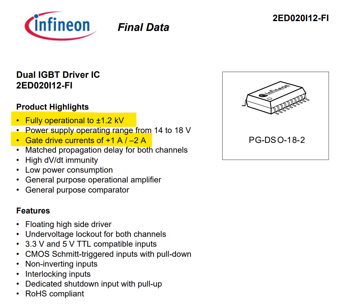
The three IGBT drivers are Infineon 2ED020I12-FI, dual IGBT drivers for one motor leg half-bridge each. It is a high side driver IC with 1200 V isolation specification and can supply +1A / -2A driving current capability. It has its own floating power supply and can accept normal 3.3V / 5V logic level inputs from a microcontroller.