Published on: 07. February 2019
This is chapter 7 of the DRSSTC design guide: MMC / resonant tank capacitor design for Tesla coils and inverters.
MMC is short for multi mini capacitor and is used to describe a resonant tank capacitor made from many smaller capacitors to achieve the needed ratings.

As with all the other aspects of designing a Tesla coil, many of the choices on component and design selection are interrelated in a non-logical way and it often makes it difficult to split up the design as I try to in this guide. That means some data and input used in selecting a MMC is based on prior choices regarding IGBT, topology or secondary circuit. For most people a MMC will first and foremost be designed from a money perspective, high power pulse rated capacitors are not cheap.
I will discuss the following three roads to take in the design of a MMC:
- Design by the DC voltage rating of the capacitor and operate as close to that as possible
- Design by peak / RMS current and temperature rise and let the DC voltage rating be satisfied as a a secondary parameter, often with more head room
- Design by peak voltage rating of the capacitor at the resonant frequency and determining the maximum allowed on-time.
1. Designing by DC voltage rating and peak current rating is a quick, dirty and easy method. The result is a working and cheap MMC, but failure at long run-times and shortened life time should be expected.
2. Designing by peak / RMS current rating and temperature rise results in a set of data where it has to be chosen what is acceptable, DC voltage rating is also a part of it and it is necessary to always adjust the design to have around 10-20 % voltage rating overhead by this method. Results in a robust and medium cost MMC.
3. Designing by peak voltage rating and maximum on-time for the current to flow in the LC circuit before the voltage rating of the MMC is hit. A conservative approach, especially if the AC voltage rating is used. Results in a indestructible but also very expensive MMC.
I use and recommend the peak current, RMS current and temperature rise method, which is also the method used in my MMC calculator. It is a more thorough result set, but I will demonstrate all three methods here.
If you are looking for a list of good MMC capacitors or the MMC calculator, follow these links. Examples and explanations from the list and the calculator will be used throughout this guide.
What is the expected life span of the Tesla coil?
The first important decision to make is what the expected life time of the Tesla coil is.
- Is it just a weekend experiment?
- Is it something you want to show to family and friends?
- Is it something you want to perform with in a show?
- Is it something that will be used on a daily basis in a museum?
The further down you get on this list, the more important it is that the Tesla coil is reliable and here the MMC is often a part that fails due to inadequate design and abuse of a underrated part that is working under great stress.
For 1 and 2 it will be okay to design simple and cheap as it will be shown in the budget example, for 3 and 4 it is highly recommended that you use the advanced and more expensive design criteria that will be shown in advanced examples.
How to choose the value of the MMC capacitance?
This choice is also revolving around the money issue, high impedance primary circuits have lower capacitance, operate at longer on-times, lower peak currents and is generally cheaper to build. Low impedance primary circuits have higher capacitance, operate at short on-times, have very high peak currents and is generally more expensive to build due to more capacitors needed to get the capacitance and appropriate voltage rating for the higher peak currents. More details on low and high impedance is also covered in Secondary coil part of this guide.
The larger a system is, the larger should the MMC also be, in order to match the energy needed to push out longer and longer sparks, more pulse energy storage is also needed.
A general guide, using the same Tesla coil sizes as in the secondary coil design part, can be seen in Table 1. I will look at five different sizes of coil systems with a rough power input estimate:
- Micro, less than 0.5 kW
- Mini, less than 2 kW
- Medium, less than 10 kW
- Large, less than 20 kW
- Very large, more than 20 kW
| Coil diameter | Coil length | Capacitance range | |
| Micro | 40 mm 50 mm | 160-200 mm 200-250 mm | 0.1 – 0.2 uF |
| Mini | 75 mm | 300-375 mm | 0.15 – 0.45 uF |
| Medium | 110 mm 160 mm | 440-550 mm 640-800 mm | 0.3 – 0.6 uF |
| Large | 200 mm 250 mm | 800-1000 mm 1000-1250 mm | 0.45 – 1 uF |
| Very large | 315 mm 400 mm | 1250-1575 mm 1600-2000 mm | 0.6 – 2 uF |
1. How to design a MMC based on DC voltage rating and primary peak current
I find that the easiest way to design a DRSSTC primary circuit is so choose a maximum primary peak current that the IGBTs can handle and then design the MMC from this. So with a known value in the following example, I will demonstrate how to design a 0.45 uF MMC for use in a 70 kHz coil with 800 Ampere peak primary current, a medium size system that can produce somewhere around 1.5 to 2 meter sparks.
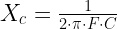
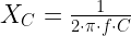
First we need to calculate the reactance of the MMC, F is frequency in Hertz and C is capacitance in Farad.
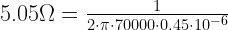
Now we can calculate the impedance of the MMC, ESR is the combined ESR of the series and parallel connected capacitors in the MMC. For the 0.45 uF MMC I chose to use 6 parallel strings of 2 CDE 942C20P15K-F capacitors in series. Each capacitor has a DC voltage rating of 2000 V and a ESR rating of 5 mΩ, which results in 4000 V series rating and a 1.66 mΩ rating for the chosen MMC.
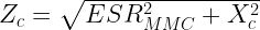

As it can be seen, with low ESR polypropylene pulse capacitors, the ESR is almost negligible when calculating the impedance.
Last we can calculate the peak voltage across the MMC and see if it is higher or lower than the combined series VDC rating of the capacitors. Zc is the MMC impedance from above and primary peak current in Ampere.


The multiplied DC rating of the capacitors in series is just on spot of what is needed to run the system at 800 Ampere peak. You can now just adjust the primary peak current in this last formula to find out when you will be below or above the voltage rating of your MMC.
2. Designing a MMC based on peak current, RMS current and temperature rise
This will be a fairly long part, as the calculations and explanations will go hand in hand with my MMC calculator, as that is the tool I made after this design method but also to give a more in-depth introduction to those that use the MMC calculator.
This method is based on designing a MMC from a certain maximum peak current, as the IGBTs often is a set-in-stone parameter and they are the limiting factor in the design.
Then there is seven important capacitor specifications in order to get the most precise results. It is Capacitance, Voltage rating, Peak current rating, RMS current rating, dV/dt rating, ESR rating and specific dissipation factor. These values also have to be calculated / extrapolated for the chosen resonant frequency. Help on getting these values can found bottom of the good MMC capacitors list.
Input parameters for the Tesla coils primary circuit is also important to be able to calculate the ratings of the MMC. When all these numbers have been plotted in, it is just as simple as using the +/- buttons to adjust number of capacitors, on-time, BPS or primary peak current to see that the results are equal to or better than the requirements.
To use the same example I will once again use the 0.45 uF MMC where I choose to use six parallel strings of two CDE 942C20P15K-F capacitors in series. Each capacitor has a DC voltage rating of 2000 V in a 4000 V series rating. A MMC to be used in a 70 kHz coil with 800 Ampere peak primary current.
We can reuse the calculations and results from the example above, so we can continue from where the calculated MMC impedance is 5.05 Ω and peak voltage across the MMC is 4040 V.
Steve McConner proposed the following equation to calculate the RMS current across the MMC based on a square waveform, BPS and on-time


The 6 parallel strings of CDE 942C20P15K-F capacitors, which has a 13.5 A RMS current rating each, gives us a 81 A rating, so the actual load is just shy of hitting the rating, so we should think seriously about limiting on-time, BPS, peak current or overall run times lengths. The peak current rating of these capacitors are 432 A each, so multiplied by 6 strings in parallel that gives us a total peak current rating of 2592 A which is with plenty of headroom in respect to the 800 A peak current we planned to run this coil at.
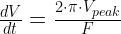
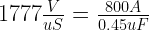
We also need to check that the rate of voltage change across the MMC does not exceed that rating of the MMC. First we calculate the actual dV/dt imposed on the MMC. V is peak DC voltage over MMC and F is frequency in Hertz. This will give a result in V/uS.

The actual dV/dt rating of the MMC is a simple equation and this number have to be higher than the above calculated imposed dV/dt. Primary peak current in A and MMC capacitance in F.

In this case there is plenty of headroom for the dV/dt.
The last step to ensure that we have a sturdy MMC that can be operated for extended periods of time is to calculate the temperature rise of the single capacitor according to its dissipated power.
First we need to calculate the dissipated energy in a single capacitor for a 1 second time period. So this means we divide the combined Irms result of 80A from earlier with the six strings in parallel and that gives us 13.33A.


Temperature rise for a single capacitor can now be calculated, this now the last simple task of multiplying the dissipation with the dissipation factor. For this example I have it given in the datasheet as 11ºC/W, which means that this capacitor will rise 11ºC for each 1 Watt of power dissipation. If you can only find a rating given in W/K, look at the bottom of this page on how to convert that value.


While almost 10ºC does not sound like much, we have to remember that this is for a single second of operation. It is important that we let the capacitor be able to cool down enough between pulses that the temperature does not just keep adding up until disaster happens.
To give a better idea of how much is tolerable, here is a rule of thumb list for temperature rise per second.
- 0 – 5 ºC = Very good
- 5 – 10 ºC = Good
- 10 – 15 ºC = Not good
- 15+ ºC = Bad
3. Designing a MMC based on peak voltage rating and maximum on-time
This path of design is from Matt “Sigurthr” Giordano and he starts his design by asking two questions, “how long a burst length can I use?” and “which voltage rating do I need on the tank capacitor?”.
This is not so much designing a MMC, but more a method to check how hard you can drive a existing MMC without damaging the capacitors.
Maximum on-time in uS and the voltage rating needed for the MMC are inter-related, but the link is not straight forward as it has to do with some inductive load inverter theory.
Each half cycle the inverter switches polarity it adds more voltage, and thus more current is flowing into the tank circuit. The longer your burst length, the more the voltage and current can ring up. So, how do we know when voltage or current is too high?
We would like to know the maximum primary peak current that we can adjust our OCD circuit to. This is dependent on the voltage we will allow according to the voltage de-rating that we choose for the MMC capacitors. Here we can either use the AC voltage rating or use the DC voltage rating with a head room between 20 to 50%.
So to avoid damage to the MMC, we can limit the voltage across it by calculating a OCD maximum peak current value and determine what the maximum on-time is before the voltage is so high that the interrelated current is too high aswell.
These calculations disregard the fact that primary current is, in normal operation, limited by the secondary arc load. A well tuned and built coil should never have its OCD trip as all the energy should be transferred into making sparks.
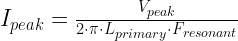
To use the same example I will once again use the 0.45 uF MMC where I choose to use six parallel strings of two CDE 942C20P15K-F capacitors in series. Each capacitor has a DC voltage rating of 2000 V in a 4000 V series rating, but for protection I will de-rate that 20% so the calculations are done with a maximum allowed 3200 V across the MMC.
Peak voltage V_peak is given in Volt, Primary inductance L_primary is given in Henry and frequency F_resonant is given in Hertz.
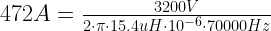
The result shows with good precision why I ran my DRSSTC1 at 500 Ampere OCD settings, as this corresponds to the low voltage rating of the MMC, but not lower than it was a good match with the IGBTs used.
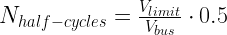
The maximum on-time to stay below 3200 V across the MMC, and thus also stay below 472 A peak primary current can be calculated, but it is dependent of the inverter type.
The maximum on-time for a half-bridge
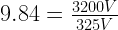
10 half-cycles at 70 kHz on a half-bridge, according to table 2 is around 72 uS before we have either 3200 V across the MMC or 472 A flowing in the primary circuit.
The maximum on-time for a full-bridge
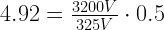
5 half-cycles at 70 kHz on a full-bridge, according to table 2 is around 35 uS before we have either 3200 V across the MMC or 472 A flowing in the primary circuit.
The table below can be used as reference for these calculations, as a general lookup table instead of calculating the time half a period lasts at a given frequency or just for sanity check of your own calculations.
| Halfcycles: | 1 | 2 | 3 | 4 | 5 | 6 | 7 |
| 40 kHz | 12 | 25 | 37 | 50 | 62 | 75 | 87 |
| 60 kHz | 8 | 17 | 25 | 33 | 41 | 50 | 58 |
| 80 kHz | 6 | 12 | 18 | 25 | 31 | 37 | 43 |
| 100 kHz | 5 | 10 | 15 | 20 | 25 | 30 | 35 |
| 150 kHz | 3 | 7 | 10 | 13 | 17 | 20 | 23 |
| 200 kHz | 2 | 5 | 7 | 10 | 12 | 15 | 17 |
| 250 kHz | 2 | 4 | 6 | 8 | 10 | 12 | 14 |
| 300 kHz | 2 | 3 | 5 | 7 | 9 | 10 | 12 |
| 350 kHz | 1 | 3 | 4 | 6 | 7 | 8 | 10 |
| Halfcycles: | 8 | 9 | 10 | 11 | 12 | 13 | 14 |
| 40 kHz | 100 | 112 | 125 | 137 | 150 | 162 | 175 |
| 60 kHz | 66 | 75 | 83 | 91 | 100 | 108 | 116 |
| 80 kHz | 50 | 56 | 62 | 69 | 75 | 81 | 88 |
| 100 kHz | 40 | 45 | 50 | 55 | 60 | 65 | 70 |
| 150 kHz | 27 | 30 | 33 | 37 | 40 | 43 | 47 |
| 200 kHz | 20 | 22 | 25 | 27 | 30 | 32 | 35 |
| 250 kHz | 16 | 18 | 20 | 22 | 24 | 26 | 30 |
| 300 kHz | 14 | 15 | 16 | 18 | 20 | 21 | 23 |
| 350 kHz | 11 | 13 | 14 | 15 | 17 | 18 | 20 |
| Halfcycles: | 15 | 16 | 17 | 18 | 19 | 20 | 21 |
| 40 kHz | 187 | 200 | 212 | 225 | 237 | 250 | 262 |
| 60 kHz | 124 | 132 | 141 | 149 | 158 | 166 | 175 |
| 80 kHz | 94 | 100 | 107 | 113 | 119 | 125 | 131 |
| 100 kHz | 75 | 80 | 85 | 90 | 95 | 100 | 105 |
| 150 kHz | 50 | 53 | 57 | 60 | 63 | 67 | 70 |
| 200 kHz | 37 | 40 | 42 | 45 | 47 | 50 | 52 |
| 250 kHz | 32 | 34 | 36 | 38 | 40 | 42 | 44 |
| 300 kHz | 25 | 26 | 28 | 30 | 31 | 33 | 35 |
| 350 kHz | 21 | 22 | 24 | 25 | 27 | 28 | 29 |
RMS current and MMC heating damage
RMS current rating is often overlooked as people focus on the voltage and peak current rating. Too high RMS current will slowly heat up the capacitors to a point where failure is imminent. Pay close attention to the achieved RMS current rating and be sure to honor this as well.
Capacitors with a larger physical size will often have a advantage over many smaller capacitors due to their large thermal mass, but they are also slower to cool down again.
Path resistance to each capacitor should be equal to assure equal current sharing, as it was described in Chapter 1: Rectifiers. The rectifier closest to the supply would conduct the most current, it is the capacitor closest to the load that will conduct the most current. The 40% current derating rule can also be used for capacitors in parallel to correct for uneven current sharing.

While ripple current divides among the capacitors in proportion to capacitance values for low-frequency ripple, high frequency ripple current divides in inverse proportion to ESR values and path resistance. [3]
This means that parallel capacitors in applications with low frequency load will share the current according to the capacitance of each capacitor in parallel. Whereas a load operating at a high frequency, like a DRSSTC does, the current sharing is up to ESR values and resistance of the busbar and wires in the circuit.
Here is a example from Amaury Poulain where the MMC failed from asymmetrical current sharing and the result is heating damage of the strings that carry the most current, those with the shortest current path between MMC conection terminals.


Another example of a unblanced MMC that failed due to uneven current sharing. A capacitor was melted completely apart from excessive heat dissipation.


Best practices for MMC construction
Even current sharing can easily be obtained from ensuring even length current paths between the strings in regard to the MMC connection terminals.
Amaury Poulain’s failed MMC from above was remade with better cooling and even current paths in mind.

Here is a another example of a PCB designed by Franzoli Electronics after the same principles.


Here Jeroen Van Dijk made a very compact MMC, could have better air cooling distance between the capacitors, but the even current sharing is ensured.

Here are some of my own MMC constructions and it is always important that terminals are connected in a way so that current paths are an even length.


Which capacitor types can be used in a MMC for a DRSSTC
Film and Mica capacitors are generally the best for Tesla coil tank circuit use, Mica capacitors can however be hard or expensive to find at the capacitance needed for a DRSSTC.


Lets first have a look at a comparison between some film capacitors that have ratings in the range of what we could use for a MMC.
| Film characteristics | Polyester PET MKT | Polyethylene PEN | Polyphenylene PPS MKI | Polypropylene PP FKP/MKP |
|---|---|---|---|---|
| Dielectric str. (V/µm) | 580 | 500 | 470 | 650 |
| Max (V/µm) | 280 | 300 | 220 | 400 |
| Max DC (V) | 1000 | 250 | 100 | 2000 |
| Capacitance | 100pF+ | 100pF+ | 100pF+ | 100pF+ |
| Max temp. °C | +125 | +150 | +150 | +105 |
| Dissipation factor (•10−4) | ||||
| 10 kHz | 110-150 | 54-150 | 2.5-25 | 2-8 |
| 100 kHz | 170-300 | 120-300 | 12-60 | 2-25 |
| 1 MHz | 200-350 | – | 18-70 | 4-40 |
If we solely look at the voltage rating and capacitance of a film capacitor when building a MMC, there could be problems with heat dissipation at DRSSTC frequencies. As it can be seen, polypropylene capacitors have a very low dissipation factor even at high frequencies, which makes them our preferred choice.
The FKP type of polypropylene capacitors are made from layers of film and foil, the FKP type does not have self-healing capabilities and will fail short circuit. The MKP type is made from metallized film that is self healing, if a local punch through of the film happens, the small internal explosion will burn away the metallized layer around the punch through hole and thus isolates it from the rest of the layer. This way a punch through in a MKP type will fail open circuit, which makes them our preferred choice.
Some more details on polypropylene film capacitors
The temperature and frequency dependencies of electrical parameters for polypropylene film capacitors are very low. Polypropylene film capacitors have a linear, negative temperature coefficient of capacitance of ±2,5 % within their temperature range.
The dissipation factor of polypropylene film capacitors is smaller than that of other film capacitors. Due to the low and very stable dissipation factor over a wide temperature and frequency range, even at very high frequencies, and their high dielectric strength of 650 V/µm, polypropylene film capacitors can be used in metallized and in film/foil versions as capacitors for pulse applications, such as CRT-scan deflection circuits, or as so-called “snubber” capacitors, or in IGBT applications. In addition, polypropylene film capacitors are used in AC power applications, such as motor run capacitors or PFC capacitors.
Most power capacitors, the largest capacitors made, generally use polypropylene film as the dielectric. Polypropylene film capacitors are used for high-frequency high-power applications such as induction heating, for pulsed power energy discharge applications, and as AC capacitors for electrical distribution. [1]
A word on physical dimensions of capacitors for either DC link or MMC
As demonstrated by El-Husseini, Venet, Rojat and Joubert in their article “Thermal Simulation for Geometric Optimization of Metallized Polypropylene Film Capacitors”, the physical geometry of a capacitor can have an impact on capacitor temperature, power loss and life. They demonstrated that for the same electrical stress, taller capacitors experienced higher temperature and losses than shorter capacitors.
As stated in their article, in taller capacitors, the current must travel a longer distance through the very thin metal films, thus the total I²R is higher compared to a short capacitor. The authors demonstrated that the total power loss in the capacitor is
proportional to Equivalent Series Resistance (ESR) and to the square of the true RMS current. ESR represents the eddy current and dielectric losses, which are affected by both frequency and current. If capacitor current is elevated, power loss increases. Likewise, power loss in a metallized film capacitor increases if the frequency of the current increases. Thus, harmonic current flowing in a metallized film capacitor, the power loss will be higher than if pure sinusoidal current were to flow. [2]

Cooling of capacitors by forced air can be a solution to get a longer life time.
Approximately 2/3 generated heat rise moves out axial and 1/3 radial.
So it is most important to cool a capacitor at its terminals as it does not radiate the heat evenly from all over its surface.
The thermal resistance (Rth) from case to ambient is given for still air in most datasheets, so if forced air cooling is used the thermal resistance can be de-rated. Some manufacturers supply equations to calculate a exact thermal resistance in regard to capacitor surface and forced air speed velocity.
How to read capacitor datasheets and calculate missing values
Capacitive reactance Xc, where f is frequency given in Hertz and C is capacitance given in Farad
ESR can be calculated from the tangent of loss angle given as TANδ in the data sheets. ESR is frequency dependent. C is capacitance given in Farad, f is frequency given in Hertz.

Thermal resistance (Rth) when given in data sheets are either Watt needed to raise the temperature by one Kelvin or degree Celsius the temperature raises by one Watt dissipation. Conversion from W/K to °C/W is to divide one by W/K dissipation factor.
Ipeak or Ipulse is calculated from the dV/dt rating times the capacitance of the capacitor. Capacitance given in micro Farad times pulse rise time given in micro seconds will give a result in Ampere.
As a rule of thumb ESL is about 1.6 nH per millimeter of lead distance between the capacitor itself and the rest of the circuit. This also includes the leads of the capacitor itself. This only applies to well designed capacitors.
References
[1] http://en.wikipedia.org/wiki/Film_capacitor
[2] M.H. El-Husseini, Pacal Venet, Gerard Rojat and Charles Joubert, “Thermal Simulation for Geometric Optimization of Metallized Polypropylene Film Capacitors”, IEEE Trans. Industry Appl, vol. 38, pp713-718, May/June 2002.
[3] CDM Cornell Dubilier, “Aluminum Electrolytic Capacitor Application Guide”, http://www.cde.com/resources/catalogs/AEappGUIDE.pdf
Pingback: DRSSTC design guide updated with MMC design guide | Kaizer Power Electronics
Hello Mr. Barnkob,
You left a small mistake in your first dV/dT calculation.
It should be 2pi*Vpeak*F and not 2pi*Vpeak/F.
Thank you for the great content!
-CE-
hello.
I want to use this caps for my mmc MKS4U031506G00KSSD, this are 0.15uf at 2kvdc, i want to put two parallel strings of three capacitors , this will give me a total of 0.10uf at 6kvdc.
Do yo think that are good caps for an mmc?
Hi Zanik
It is a PET material capacitor and they have a pretty dramatic voltage derating for AC at high frequency and PET has a high dissipation factor. So you risk having a MMC that will heat up fast and will need a lot of forced air cooling.
It will work, but it will have shorter life time than a MKP material type MMC.
Kind regards
Mads
6000 volt nps at 30ma cycling @60hz
please help
can i use 20kv 0.05-0.5 if so i still dont know about strings
Hello I have problems calculating the peak current of my LC circuit. I am looking for formulas that will help. This was very helpful but i noticed you calculated about 472 amps. I have a 15,000 volt 30 ma transformer and its not big enough for my tesla coil. 472 amps is way to much for a 30 ma transformer. What size transformer do you use for this mmc and how could i calculate this. Thanks
Hi john ostler
I do not build that many SGTC, so I do not use neon transformers, I do solid state inverters with IGBTs and such.
That being said, you still need a large peak current handling capability in a spark gap Tesla coil, the 30 mA rating of the transformer does not have much to do with the energy circling in the LC circuit.
For calculating the correct MMC for a SGTC, use JavaTC MMC calculator, scroll down to “power calculations”: http://www.classictesla.com/java/javatc/javatc.html
Kind regards
Mads
Thanks for the resource. Mind lending some advice?
From looking at my college notes, for a series resonant circuit:
At resonance, Xc = Xl, which oppose one another leaving the impedance at resonance Z= R.
From here the current in the primary is given by : I=V(bus)/R
..this gives crazy high values for primary current and volt drop across components.
Can you explain why my workings are incorrect?
Many thanks
Hi Tom
Primary peak currents are very high! But they are also only grown up to the high level, one cycle at a time of the resonant frequency, at up to some 200 uS on time. So your calculations are most likely correct.
Kind regards
Mads
Has the voltage across the capacitor ever been directly measured? I somewhat understand your Vpeak reasoning, assuming a current and multiplying by impedance (v=ir). When designing a standard spark gap tesla coil, the voltage rating of the capacitor is simply the ac voltage rating of the supply. A 15kv nst would require a 25kv cap bank accounting for peaks. I just don’t see how a bus voltage of 325v requires a cap bank rated at 4000v! With a break out point on the secondary there shouldn’t be ring up in the primary? Once again the capacitor is the most expensive component when maybe it shouldn’t be?
Pingback: DRSSTC MMC design guide
Hi Mads,
there is a small mistake in your dV/dT calculations, with exact same numbers that you put in there i get result equal to 0.35903916. Even by moving order of magnitude higher it’s still off
(continuation of previous message)
Charles above was right
with method written in your tutorial it came out as:
[Hz] = 1/s
[dV/dt] = [V/Hz] = [V/(1/s)] = [Vs], not [V/s] how it was suppose to be
I think proper method should look like this:
[dV/dt] = [V*Hz] = [V*(1/s)] = [V/s]
(I omitted unnecessary constants)
Hi Caraffa
I think my errors goes a bit deeper. The MMC rating dv/dt calculation also uses the primary peak current and not the MMC peak current rating. This is all reflected into the MMC calculator as well, where the calculation for MMC rating is actually the correct one for what the should be in the actual values. https://kaizerpowerelectronics.dk/calculators/mmc-calculator/
70000 hz, with your correct formula
2527 v 1111 dv/dt
For MMC calc (dVdtRating=((peakcurrent/(mmcCapacitance/1000000))/1000000); )
2592A and 0,15 uf
17280 dv/dt
Would love if you could double check before I make the corrections 🙂
Kind regards
Mads
Hi Mads,
I don’t really know if my formula is correct. I thought it was just slight mistake, so it was more as a guess based on units of variables used in the previous formula.
If my guess is correct then yes, your calculations seem fine but i would skip dividing by 1000000 in second part bc it cancels itself out anyways.
((peakcurrent/(mmcCapacitance/1000000))/1000000)) = peakcurrent/mmcCapacitance (in uF)