Published: April 5, 2016. Updated May 7, 2022.
Introduction
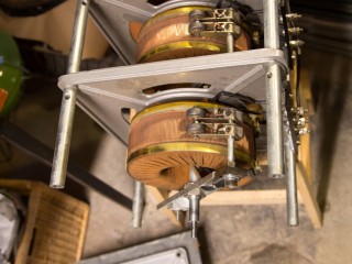
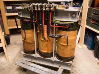
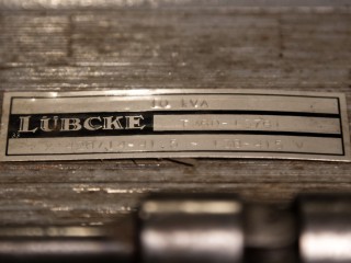
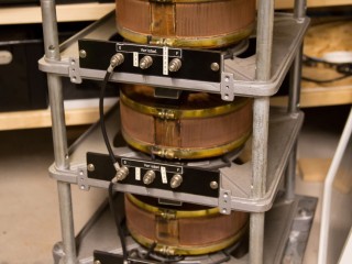
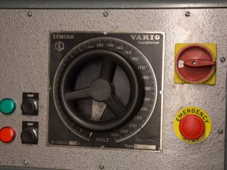
On a junk yard I found a badly damaged enclosure containing a 3 phase 13 A Lübcke variac, 10 kVA isolation transformer and 6 large stud diodes in a 3 phase full bridge rectifier configuration.
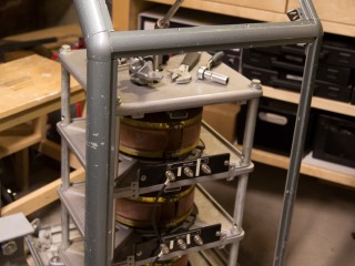
It was not possible to save the entire enclosure, so I saved what could be saved, which resulted in enough of the original enclosure to rehouse the variac itself and isolation transformer and rectifiers would have to be installed in a separate housing.
Safety
WARNING!: Working with electricity is dangerous, all information found on my site is for educational purpose and I accept no responsibility for others actions using the information found on this site.
Read this document about safety!http://www.pupman.com/safety.htm
Considerations
The damaged enclosure could no longer contain all 3 parts, which for the sake of experimental setups and moving it all around, is not that a bad idea at all. Just the isolation transformer itself weighs around 100 kg. By building a modular system I could put the 3 different parts together in any configuration needed.
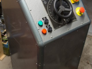
New safety features will be added, start/stop buttons and a emergency stop to break the same connection as the start/stop, but it will also prevent starting again without reset of emergency switch.
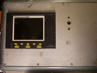
Measurement of all 3 phase voltages and currents will be installed in the top panel.
Specifications Lübcke Variac
| Variac | Lübcke variac Vario Transformer 0 – 250 VAC at 13 A |
| Isolation transformer | Lübcke T360-|376| at 10 kVA Input: 3x 420 VAC Output: 3x 138 – 415 VAC |
| Data monitor | PMA data monitor KS4010 6 analogue inputs, 125 ms sample rate |
Lübcke Variac Schematic
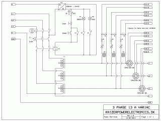
Mains voltage schematic with start/stop, safety and emergency switch. Step down transformers for voltage measurement and current transformers are also shown.
Lübcke Variac Construction
16th February 2013
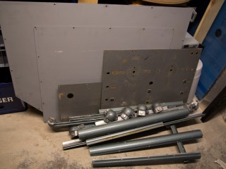
I spent a day taking the old enclosure apart at the junk yard, sawing it up in smaller undamaged pieces that could be used to rebuild a smaller enclosure.
It took 3 trips to bring home the 3 phase 13 A variac stack, the 10 kVA isolation transformer and all the enclosure skeleton and shielding.
23th February 2013
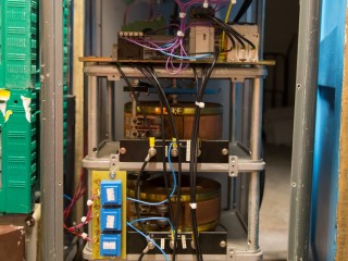
I dismantled as many parts as possible of the Lübcke variac and transformer in order to inspect for damages, clean them and put it back together securely.
The terminals on the transformer was all bend and a handful of them was destroyed and needs to be changed. Bridge rectifier is in a perfect shape and needed nothing more than having dust removed.
1st June 2013
I found a heavy metal rolling board with 4 wheels on that could easily carry the heavy load from the variac and it would be easy to install the enclosure on the rolling board.
It was a fairly straight forward job to get the enclosure skeleton back together, I only ended up being one piece short that I had to put together from two smaller pieces, as I used the joined pieces down by the roller board it is nothing that will ever be noticed, mechanically the strength of it is not compromised.
22nd November 2013
I had an old PMA data monitor KS3010 that I wanted to install for measurement of voltage and current on all 3 phases. The data monitor has 6 analogue input channels for signals in the range of +/- 12 VDC and samples these values as a average over 125 ms, which corresponds to 8 samples per second. It can also export historical data on a 1.44″ floppy disk.
For the voltage measurements I used 400 VAC to 20 VAC step down transformers acquired on ebay and through a single diode and a resistor voltage divider getting it to a level that the data monitor can work with.
I planned at first to measure the current with regular current transformers, but the average voltage from a current transformer of a sine wave current resulted in completely wrong values shown and there was no parameters on the data monitor to make up for the signal condition. I would have to make a peak detector with sample and hold function, that also resets itself to work with the 125 ms sample rate of the data monitor.
28th December 2013
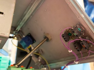
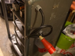
Wiring of start/stop, emergency stop, lockable mains switch, relay,circuit breaker and output terminals was made.
24th July 2015
I made an experiment with Allegro ACS758 hall effect current sensors used in mains current detection, it was unidirectional 100 A sensors that has an output sensitivity of 40 mV/A. The problem with them was however the output always being Vcc/2 and the current waveform is represented as a sine wave positive and negative from this, at a very high sample rate. Unfortunately again a signal that did not work with the old data monitor. Instead of building a interface for a low signal hall effect current monitor I decided to go back to regular current transformers and a peak detector with hold, sample and reset circuit.
29th November 2015
Peak detector design is used from my 2000A current monitor design and a PCB with 3 of the peak detectors with hold and sample on and a common reset function has been designed. This did work, but I was once again stuck with peak current measurements. Prices on RMS calculation ICs are not favourable and I started looking into alternatives like RMS current transducers.
15th August 2016
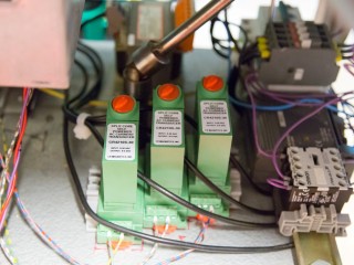
I finally managed to find some affordable AC RMS current transducers with a 0-5 VDC output signal. I got these at 20$ a piece off of a US based ebay seller and had to pay the import charges. This was the result after searching for over 6 months for a cheap alternative to designing a RMS circuit myself and I am satisfied as I got these at just the costs to get RMS ICs.
30th August 2016
With the new AC current transducers installed it was finally time for a test. As a test load I used a 9 kW electric heater, which at nominal voltage will draw 13 A.
There is only earth wiring to be completed to the output connector and remounting of the panel sides and this project is finished.
Conclusion
Lockable mains switch, emergency stop and data collected on the monitor makes this a very safe and versatile power supply.
Isolation transformer can be connected either before or after the variac, bridge rectifier can be connected after the variac if DC is needed.
Test with a heavy capacitive load as a Tesla coil is not yet performed.
Future add-ons could be a connector for a remote emergency stop and a dead man switch, some kind of actuator that would released upon muscle cramps.
Demonstration
30th August 2016
First demonstration of how the Lübcke Variac based power supply is built and a test with a pure resistive load from a 9 kW electric heater.
